Transforming XMI to HTML
|
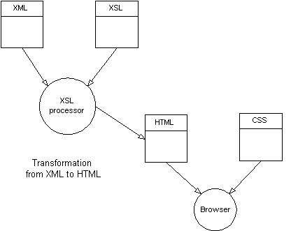
In this project we will be demonstrating how to use the newly introduced XSL stylesheet technology to transform XMI documents into HTML. Our purpose is to be able to display an object-oriented design in a web browser. XMI is an XML-based, stream representation of a UML model which has the potential to allow models to be shared between different UML tools. Since XMI is a relatively new part of the suite of UML standards (March, 1999), support for this standard will appear gradually over the course of this year. For a discussion on the future role XMI can play in the O-O development process, please see our criteria for choosing a UML modeling tool. There are a number of new, evolving technologies discussed in the sections which follow. Links to documents describing these technologies are provided at the end of this page for further research. The reader will benefit by delaying the navigation of these links until after the presentation of our design. Overview The following diagram illustrates the general process of transforming XML to HTML. |
The main driver of the XML transformation is the XSL processor. The XSL processor reads in both the XML document and the XSL stylesheet. The XSL stylesheet describes a set of patterns to match within the XML document and the transformations to apply when a match is found. Pattern matches are described in terms of the tags and attributes for elements found within an XML document. Transformations extract information from the XML document and format it into HTML. Each match/transformation pair is called an XSL template; we will soon see them in action. The transformation process works in a way very analogous to the way scripting languages such as Perl or AWK operate. In that sense XSL could really be called a scripting language, especially since it contains elements of control flow similar to a scripting language. For our project, we are using Cascading Style Sheets (CSS) to provide formating information to the browser when displaying the generated HTML. CSS provides the advantage of eliminating the repetition of many formating tags for HTML elements; instead they are extracted at display time from a style in the stylesheet. This works analogously to the way stylesheets in word processors work. Note from the diagram that the XSL transformation produces a single HTML file. This is an artifact of the way the XSL process works - there is no file control as in true scripting languages. However, we will utilize the single HTML file to our advantage - the resulting HTML, while potentially large, is loaded once and provides faster hyperlinking between elements of the O-O design, especially when loading from a web server. The XSL processor that was used for this project is an excellent Java-based, open-source tool called LotusXSL. This tool was produced by IBM's alphaworks project and is 'supported' through an active discussion newsgroup on the alphaworks site. Design Our initial goal is to get a handle on XSL and XMI. As a starting point for any XSL project, it is helpful to have a picture of what the intended HTML will look like. It is then easier to work backwords to determine which XML elements contain the information needed and to figure out which XSL constructs can be used to do the transformation. The basic UML elements we have set out to present in HTML are the class and interface elements. We also want to show inheritance from an interface or a class. For an interface, we want to show the operations and their signatures. For a class we want to show attributes as well as operations. And wherever a parameter or attribute type is defined elsewhere in the HTML document, we want a hyperlink to take us there. The resulting HTML produces something that looks like this:
Let's deconstruct this HTML to see the underlying structure. This will help later when describing the transformation process. There are basically three nested tables used here. The outer table is the container for the whole definition. The first row in this table includes the name of the element and indicates whether the element is a class or interface. The second table is used to contain the details of the element definition, in this case the attributes and operations of a class. As will be seen, this table is used to get the effect of the grey lines between table cells as well as to offset the details from the container. Therefore, the second table is nested within the outer table. The third table contains the input parameter definitions for an operation and is nested within the second table. This table allows us to offset the parameters from the operation name and to organize the parameter definitions with columns for the type and name. Model By now you are surely wondering, "So where did we get the XMI from?" Both the diagram and the XMI for this project were produced by ArgoUML, an open-source UML modeling tool developed at the University of California, Irvine (UCI). ArgoUML is still below version 1.0 (0.7) but the primary author, Jason Robbins, had the foresight to implement the model persistence using XMI. As such, it has the distinction of being one of the first UML modeling tools to implement the XMI standard. Our example application for this project is inspired by and derived from an example used by Bertrand Meyer in his book, Object-Oriented Software Construction - the modeling of geometric shapes in an editor. The example is useful because it shows the use of inheritance, which we want to demonstrate in our HTML representation of the model. The resulting diagram for the model may be viewed in a separate window: the Graphics Editor Model. Transforming our model into HTML by using the XSL stylesheet developed for this project produced the following page, shown in a separate window: HTML Rendition of the Graphics Editor Model. Now let's see how the transformation process works. Transformation The XSL transformation process begins with a processing instruction which indicates to the XSL processor the type of transformation that will take place.
<xsl:stylesheet

    xmlns:xsl="http://www.w3.org/XSL/transform/1.0"

    xmlns="http://www.w3.org/TR/REC-html40" result-ns="">
The stylesheet instruction tells the XSL processor which version of the XSL standard is used and indicates that the transformation will produce HTML output. Next follows the top-level template which is used to create the basic HTML document and to kick-off the XMI transformation.
<xsl:template match="/">

    <HTML>

    <HEAD>

    <link href="xmi.css" rel="stylesheet" type="text/css"/>

    </HEAD>

    <BODY>


    <xsl:apply-templates select="//Interface">

         <xsl:sort select="name"/>

    </xsl:apply-templates>


    <xsl:apply-templates select="//Class">

         <xsl:sort select="name"/>

    </xsl:apply-templates>


    </BODY>

    </HTML>


</xsl:template>
Notice how XSL directives are interspersed with HTML elements. This is how XSL works. It may likely be a new paradigm for many developers, one which will take a little getting used to (kind of like OOP the first time!). The XSL processor transfers the HTML elements to the transformed document and interprets any embedded XSL directives that are encountered. These directives in turn may trigger additional HTML elements to be transferred and new directives to be interpreted. And so on. In the head of the generated HTML document the CSS stylesheet XMI.CSS is linked in. We'll see how some of the styles in this stylesheet are employed further on. In true top-down fashion the transformation process begins with two XSL apply-templates directives, one to generate the list of interfaces and one to generate the list of classes. The select clause indicates to the XSL processor the elements to search for in the XMI document. In this case it is the Class and Interface elements. These are preceded by double slashes, '//', to indicate that the Class or Interface tag should be searched for starting from the root of the XMI document. Notice also the sort directive. It is used to tell the XSL processor to sort the Class and Interface elements by their names during the transformation process, giving us a nice alphabetical list in the output HTML. HTML for a Class Now let's see how the XMI for a class is transformed. The first part of the transformation creates the HTML table which contains the class definition and outputs the name of the class.
<xsl:template match="Class">

    <xsl:variable name="element_name">

    <xsl:value-of select='name'/>

    </xsl:variable>


    <div align="center">

    <table border="1" width="75%" cellpadding="2" >

    <tr>

        <td class="class-title" width="20%">Class</td>


        <td class="class-name">

        <a name="{$element_name}">

        <xsl:value-of select="name"/>

        </a>

        </td>

    </tr>
At the beginning of this template a variable, element_name is declared. The variable is assigned the value of the name of the class using the value-of directive. The purpose for defining a variable is to allow the value of the variable to be substituted by the XSL processor during a transformation. This comes into play when defining a hyperlink target for the class definition, using <a name="{$element_name}">. If the XSL processor didn't provide variable substitution, there would be no way to define the hyperlink target since an XSL directive cannot be embedded inside an HTML element (this would violate the XML syntax, from which XSL is derived). Of course, the purpose of the hyperlink target is to allow any definition in the model which references a class to quickly jump to its definition. The next portion of the XSL template generates the body of the class definition, including the attributes and operations.
    <tr>

    <td colspan="2" >

    <table width="100%" cellpadding="0" cellspacing="0" border="0">


    <tr>

        <td colspan="2" bgcolor="#cacaca">

        <table width="100%" border="0"

               cellpadding="3" cellspacing="1">


        <xsl:apply-templates select="specification" />


        <xsl:apply-templates

            select="//Generalization[subtype/XMI.reference/

            @target=normalize($xmi_id)]"/>


        <tr>

            <td colspan="3" class="class-feature">Attributes:</td>

        </tr>

        <tr>

            <td class="feature-heading" width="20%">visibility</td>

            <td class="feature-heading" width="25%">type</td>

            <td class="feature-heading" width="55%">name</td>

        </tr>

        <xsl:apply-templates select="feature/Attribute" />


        <tr>

            <td colspan="3" class="class-feature">Operations:</td>

        </tr>

        <tr>

            <td class="feature-heading" width="20%">visibility</td>

            <td class="feature-heading" width="25%">return</td>

            <td class="feature-heading" width="55%">name</td>

        </tr>


        <xsl:apply-templates select="feature/Operation" />


        </table>

        </td>

    </tr>
The first few lines here create a little HTML magic which you see web designers employ extensively for tables. Essentially, a table is used to form a background for a second, nested table in order to achieve a more refined line style in the table for the cell borders. The way this works is that the single cell in the outer table is given a background color of light grey. Then the inner table, because it has cellspacing=1, lets the grey bleed through the cell spacing to create the thin cell borders. OK, so we're having a little fun with the HTML. But that's precisely why XSL is likely to have a strong following amongst web designers, because it allows them to do what they do best, HTML, without having to struggle with a programming language. The first XSL directive in this portion is the apply-templates directive which selects the specification element. The specification element identifies any interfaces which the class implements. Next comes an apply-templates directive which selects any Generalizations in the XMI which reference this class as a subtype. The template, described later, identifies any superclasses for this class. The last two XSL directives are the apply-templates directives for the Attributes and Operations features, with their respective column headings added to the generated HTML here. Adding the column headings at this level forces the headings to appear even if these features are not present. We don't want our class definition to appear completely empty in this case. At this point let's take a quick look at one of the CSS styles to see how the stylesheet separates formating from the main HTML document. This style is applied to the headings for the Attributes and Operations features. CSS allows us to set the font and background colors, to avoid clutter in the XSL, and most importantly, to save a few bytes in the generated HTML.
.feature-heading {

	color : #000099;

	background-color:#ffffe0;

	font-family : Verdana, Helvetica;

	font-weight : bold;

	font-size : 10pt;

}
Next we will take a look at the templates which implement the generation of the class details: specialization, generalization, attributes and operations. Please continue to Part Two of Transforming XMI to HTML.
|
|||||||||||||||||||||||||||||||||||||||||||||||||||||
|
|
Copyright © 1999 Objects by Design, Inc. All rights reserved.