Middleware Architecture with Patterns and Frameworks

Chapter 7
Composition

[© 2003-2009 S. Krakowiak, Creative Commons license][pdf version][ps version]
Composing an application out of independent, reusable pieces has been a key challenge since the early days of software engineering. This chapter examines some aspects of software composition. While there is still no universally accepted definition of a software component, many projects have explored the requirements for a composition framework, and the industry has developed several technologies for building distributed applications out of components. This chapter starts with a motivation of the need for components, by pointing out the limitations of objects as application building blocks and examining the requirements of component models and infrastructures. It goes on with a discussion of the main paradigms that apply to software composition and to the description of software architecture. It then presents the main patterns used in current middleware for component support, and some examples of their use. The chapter conclude with two case studies of middleware frameworks: Fractal, an innovative proposal founded on a rigorous model; and OSGi, a service-oriented, component-based environment widely adopted by the software industry.

7.1  From Objects to Components

Developing an industry of reusable software components has been a elusive goal, since the early vision formulated in [McIlroy 1968]. The notion of a software application being built as an assemblage of parts seems natural and attractive, but its implementation raises a number of questions. What constitutes a "part"? How is a part specified and implemented? How is it connected with other parts? How is the compound application described? How can it evolve? These questions and related ones are the subject of software architecture [Shaw and Garlan 1996], a developing area of software engineering that covers such topics as architecture description languages, configuration management, and dynamic reconfiguration.
There is no single, agreed-upon definition of a software component. This is hardly surprising, for two main reasons: the different kinds of "components" found in the research literature or in industrial products have been designed in response to different sets of requirements; and many aspects of software composition, both fundamental and practical, still need to be clarified. Before concentrating on requirements and specific issues, we start with a few definitions.
A frequently cited definition is that of [Szyperski 2002]:
A software component is a unit of composition with contractually specified interfaces and explicit context dependencies only. A software component can be deployed independently and is subject to composition by third parties.
We complement this definition with the following ones, borrowed from [Heineman and Councill 2001] (we have modified their definition of "software component infrastructure").
A software component is a software element that conforms to a component model and can be independently deployed and composed without modification according to a composition standard.
A component model defines specific interaction and composition standards. A component model implementation is the dedicated set of executable software elements required to support the execution of components that conform to the model.
A software component infrastructure,1 or framework, is a software system that provides the services needed to develop, deploy, manage and execute applications built using a specific component model implementation. It may itself be organized as a set of interacting software components.
While these definitions are quite general and need to be refined (which we do in the following sections), they are complementary. Both agree on the role of a component as a unit of independent deployment; [Szyperski 2002] stresses explicit dependencies and contract-based specifications (contracts are implied by the notion of an interface, see 2.1.3 ), while [Heineman and Councill 2001] point out the need for a component model, a composition standard, and a component infrastructure.
More precisely, several levels of component models may be considered (Figure 7.1).
Chapters/Compo/Figs/model.jpg
Figure 7.1: Component models
An abstract model defines the notion of a component and the related entities, together with their mutual relationships (naming, binding, inclusion, communication). This model may or may not have a mathematical foundation.
A concrete model defines an actual representation for the above entities and relationships. For example, communication and binding may be specified in terms of interfaces, method calls, signals, etc. A given abstract model may have several different concrete representations (for example, communication may be based on message passing or on procedure calls; binding may be static or dynamic). A concrete model may be complemented with a type system, which allows properties to be specified and verified for binding and communication, thus increasing the safety of applications.
In turn, a concrete model may have specific implementations for different programming languages. Examples of abstract, concrete, and language-specific models are provided in this chapter.
   Object-based frameworks, as presented in Chapter 5 , are a first step towards a software composition model. They provide encapsulation, i.e., separation between interface and implementation, and mechanisms for software reuse, in the form of inheritance and delegation. However, they suffer from a number of limitations, which have motivated the current developments towards a component model.
Two main consequences follow: (a) some parts of the life cycle are not adequately covered, and application evolution is problematic, in the absence of global description facilities; and (b) application developers must explicitly take care of such system-related services as persistence, security and transactions, in addition to the application-specific functionalities. This has the following drawbacks.
In order to overcome the above limitations, the goal of component-based systems2 is to enhance reusability by shifting work from development to integration, to provide generic support for common services in order to allow the developers to concentrate on the application's needs, and to facilitate application maintenance, evolution and administration.
The need for a conceptual basis for software composition has been perceived for a long time. However, different models have been developed in response to the various requirements of software design, configuration, and maintenance. The need for a common, unified model suited for all phases of the software life cycle is now recognized (see [van der Hoek et al. 1998]). Our presentation aims at exposing such a common view.
The rest of this chapter is organized as follows. In Section 7.2, the main requirements for a component model are developed. The main paradigms of software composition are introduced in Section 7.3, and the elements of a component model are presented in Section 7.4. Section 7.5 describes the main patterns and frameworks found in current infrastructures for component systems. The final sections present case studies of recent systems.

7.2  Requirements for Components

The requirements for a software development system based on components are motivated by the needs of application designers and users, which cover all phases of the software life cycle. We separate the requirements of the component model proper from those of the supporting infrastructure. However, the two sets of requirements are not independent: some features of the model need support from the infrastructure, while some functions of the infrastructure rely on aspects of the model (e.g., administration uses evolution and adaptation). This analysis is inspired, with some variations, by [Bruneton et al. 2002].

7.2.1  Requirements for a Component Model

The requirements cover the following aspects: encapsulation, composability, global description, reusability and evolution.
Encapsulation.  
The first requirement for a component model, encapsulation, stems from the need for independent composition. It has already been formulated in Chapter 5 . Encapsulation means that the only way to interact with a component is through one or several well-defined interface(s) provided by the component. An interface specifies a set of access points, to be used according to prescribed rules (e.g., read-only for an attribute, synchronous call for a procedure, etc.). No element of the internal structure of the component should be revealed, other than those which are part of the interface, and the user of the interface should not rely on any assumption about its implementation. The set of interfaces provided by a component actually defines the services that this component makes available to other components.
Composability.  
The second requirement is composability, the capability for a component to be assembled with other ones (the result of this assembly process is called a configuration). This requirement may be further refined as follows.
In summary, the following relationships have been identified: between components: depends on, is part of, contains; between interfaces or between components: conforms to; between component and interface: provides, requires. A component model should provide specific, precise definitions of these relationships.
Global Description.  
The third requirement is the need for global description capability, i.e., a high-level description of the overall structure of the application in terms of compositional entities such as components and connectors (more details in Section 7.3). This description should respect the encapsulation principle, i.e., it should not be concerned with the implementation details of the individual components.
The notation used may take different forms, e.g., one of the varieties of architecture description languages (ADLs). The composition relations defined above need to be made explicit in a global description.
Reusability.  
Components should be reusable, in order to capitalize on the resources invested in their development. Reuse entails some degree of variability to adapt to different requirements. Therefore there is a need for a form of component prototypes, or templates, which allows for well localized modifications while preserving the essential features of the component's design.
Evolution.  
An application made up of an assembly of components should be able to evolve in response to changing user needs and operating context. The evolution capability should apply both to individual components and to the configuration as a whole. It may take different forms.
Adaptation and reconfiguration are further examined in Chapter 10 .

7.2.2  Requirements for a Component Infrastructure

The requirements apply to application management and to common services.
Application Management  
The capabilities of a component infrastructure should not be limited to application development, but should also apply to application management, which covers the following aspects.
These various aspects of application management are examined in Chapter 10 .
Common Services.  
Common services are concerned with properties usually known as extra-functional (2.1.3 ). This term refers to properties that are not directly expressed in the components' interfaces; but this situation is bound to change, as interface descriptions may eventually evolve to cover these properties as well. It is more appropriate to characterize extra-functional properties as being of a general nature, not directly related to the specific functions of an application. Such properties are supported by the environment in the form of reusable services, which are common to all applications, although they may be adapted to each application's specific needs. Usual instances of common services are the following.
A component infrastructure should provide common services to the applications. The application developer should be able to specify the required services, but should not be concerned with the actual provision of these services to the application. In other terms, the implementation of the services and the insertion of the needed calls in the code of the application should be in charge of the infrastructure. This is an application of the general principle of separation of concerns (1.4.2 ).
  
No current component-based system actually satisfies all of the above requirements. For instance, the component models used by current industrial component systems fail to satisfy the closure and containment requirements (e.g., in Enterprise JavaBeans, an assembly of several beans is not a bean). Few component models support shared components.

7.3  Architectural Description

This section is an introduction to the main paradigms of software composition, from an architectural point of view, i.e., with focus on structural properties, not on implementation aspects. This presentation is intended as a general framework for the definition of component models, not as a description of a specific model. A given model does not necessarily embody all aspects of this framework.
It is important to note that the elements described in this framework not only exist as design and description elements, but remain visible as run-time structures. In other words, the notion of a component is preserved at run time as an identifiable entity. There are two main reasons for this.
This is contrary to the situation of many environments based on modules or objects, in which these entities only appear at the source code level and are not present as such in the run time structures.

7.3.1  Compositional Entities

A compositional architecture defines the global organization of a software system as an assembly of parts. It can be described in terms of components (the parts), connectors (the devices that connect the parts together), and composition rules. While many architectural models have been proposed, these notions are common to all models.
Note that the difference between components and connectors is one of function, not of nature: a connector is a special instance of a component that acts both as a binding object and as a communication channel between other components. It is a matter of convenience to make a distinction between the "ordinary" (or functional) components, which implement the functions of an application, and the communication components, or connectors, whose function is to ensure communication (and possibly interface adaptation) between the functional components. The main benefits of making this distinction are to isolate the issues related to communication (another instance of separation of concerns), and to exhibit a number of generic communication patterns, as described in Section 7.3.3.
A taxonomy of connectors has been proposed in [Mehta et al. 2000]. According to it, a connector provides a service that combines four aspects: communication (data transmission), coordination (transfer of control), conversion (interface adaptation), and facilitation (provision of extra-functional services to facilitate the above interactions). The taxonomy defines the main types of connectors (e.g., procedure call, event, stream, etc.) and specifies, for each type, the dimensions that characterize it (e.g., parameters, invocation mode, etc. for a procedure call).
With the compositional approach, an application developer constructs an application by integrating existing and new components, using the appropriate connectors. Therefore tools are needed to generate connectors and to adapt and combine existing ones. Binding factories (3.3.2 ) provide such tools for the most common cases (e.g., stub generators). Specific tools for adapting and combining connectors use the techniques for software adaptation described in 2.4 , as illustrated in [Spitznagel and Garlan 2001].

7.3.2  Architecture Description Languages

After defining the entities that allow a complex system to be composed out of parts, the next step is to describe the global structure of a compound system, using these entities as building blocks. A number of notations, known as Architecture Description Languages (ADL) have been proposed to that effect. This section is a brief review of this area.

ADLs: Objectives and Main Approaches

An ADL is a formal or semi-formal notation that describes the structure of a system made of an assembly of components, with the two following main goals.
As is apparent from the second item above, a number of different aspects may be represented in an ADL, in addition to the structural aspects proper (i.e., the parts and their connections). It is therefore not surprising that little consensus has been achieved on what aspects of the architecture should be represented. Likewise, there is no general agreement on the degree of formality that an ADL should provide.
Considering the wide range of potential uses of an ADL, three approaches may be taken.
  1. Defining a single, general purpose ADL, with sufficient flexibility to capture all potentially relevant aspects.

  2. Defining a set of specialized ADLs, each tailored to answer a specific need.

  3. Defining a core ADL, together with extension mechanisms to adapt the language and its associated tools to changing requirements.

The first approach has been followed by Acme [Garlan et al. 2000], with the objective of providing a generic format for the interchange of architectural designs. Acme also serves as an architecture description language in its own right, and provides a certain degree of extensibility through properties (in the form of arbitrary name-value pairs) attached to its elements.
The second approach has given rise to a variety of specialized languages and tool-sets, which may be classified in two main groups according to the services provided by the tools:
While each language may be well adapted to its purpose, the different languages are mutually incompatible and lack extensibility. A form of specialization is to design an ADL as an extension to a particular programming language, thus ensuring conformity between architectural description and implementation. An example is ArchJava [Aldrich et al. 2002], an extension to Java.
The third approach seems to be the most promising one, since the extension capabilities are not limited by a priori decisions. The XML metalanguage is generally used as a base for extensible ADLs ([Dashofy et al. 2002] discuss the benefits of this approach). Examples of such extensible ADLs are xADL [Dashofy et al. 2005] and the Fractal ADL (7.6.3).

ADL Design Issues

As many research groups developed ADLs in the 1990s, experience was collected on the main issues arising in the design of these languages. A summary of this experience, together with a classification and comparison framework for ADLs, has been published in [Medvidovic and Taylor 2000]. We give a summary of their main conclusions.
An ADL is based on the three notions (component, connector, configuration) introduced in 7.3.1. As mentioned earlier, there is no difference in nature between connectors and components; therefore the main design issues are the same for both entities, and are related to the requirements outlined in 7.2. These issues are interfaces (the interaction points between a component or connector and the outside world); types (formally expressed, verifiable properties); and semantics (the description of the entity's behavior, which may or not be formal). Since in the current state of the art the expressiveness of specifications and type systems is limited, two additional issues are constraints (properties that characterize a system's acceptability, and which are not captured by the type system) and non-functional properties (properties that cannot be derived from the specification of an entity's behavior expressed in terms of its interfaces). These last two aspects are also applicable to configurations.
Specific issues for configurations are understandability; compositionality (allowing a system's structure to be represented at different levels of detail, by grouping subparts in a single component); refinement and traceability (enabling the correct and consistent refinement of an architecture into an executable system, and tracing modifications across the levels of refinement); heterogeneity, scalability and evolvability; and dynamism (the ability to modify a system's architecture while the system is running, and to model those changes in the architecture's description).
Finally, a group of issues are related to tool support. This aspect refers to the ability of an ADL to serve as a common representation used by a set of tools. The main functions identified for an ADL-based tool-set are the following:
Active specification (preventing or detecting errors by analyzing a system's description); multiple views (providing different representations e.g., textual and graphical, of a system's description); analysis (establishing syntactic and semantics correctness, simulating the behavior, verifying conformance to constraints); implementation generation; support for dynamic modification.
At the time of the above survey (2000), the main deficiencies identified in the capabilities of the existing ADLs were in the following areas: support of non-functional properties; architectural refinement and constraint specification; and support for architectural dynamism.

Evolution of ADLs: Trends and Prospects

The main trends in the evolution of Architecture Description Languages may be summarized as follows.
The above discussion was limited to the technical aspects of ADLs. However, other aspects such as domain specificity and business concerns are taking an increasing importance. See 7.3.4 for a discussion of this point.

7.3.3  Examples of Connection Patterns

We illustrate the main notions related to composition with simple examples, using graphical descriptions. While most of the existing notations are equivalent (i.e., they have the same expressing power), no universally accepted standard has yet emerged, as explained in Section 7.3.2. The notation that we use freely borrows elements from the ODP model (as illustrated in [Blair and Stefani 1997]), from the OMG notation for the CORBA Component Model [CCM ], and from the Fractal component framework [Bruneton et al. 2002].

Client-Server Systems

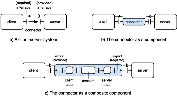
The first example is that of a client-server system using a synchronous request-response communication scheme such as RPC or Java RMI. The client requires a service, defined by an interface (for this example, an interface is a set of methods, defined by their signatures). The server provides an interface that conforms to that required by the client. The client and server interfaces are linked by a connector, as illustrated on Figure 7.2a.
Chapters/Compo/Figs/client-server.gif
Figure 7.2: A client-server system
Another view of the same system is represented on Figure 7.2b, which shows the connector as a component. Note that the connector has interfaces, which must conform to the corresponding interfaces of the client and the server.
A more detailed view (Figure 7.2c) shows the connector as a composite component, i.e., an assembly of three subcomponents: the client stub, the server stub, and a session object used for remote communication (this latter can again be further decomposed, see Chapter 4 ). Note that the provided interface of the connector is connected to the provided interface of the client stub by an "export" connector (noted as a dotted arrow); in this case, this connector does nothing apart from making the interface visible, but it could, for instance, perform an interface adaptation, i.e., exporting a different (conformant) interface. Similarly, the required interface of the connector is exported from the server stub.
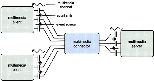
Other sorts of interfaces are illustrated in the next example, which describes a multimedia client-server system (Figure 7.3). There are two main differences with the previous example.
Chapters/Compo/Figs/multimedia.gif
Figure 7.3: A multimedia system
The multimedia connector encapsulates the various functions needed to exchange and to synchronize multimedia data between the server and the clients. This is a fairly complex system, and it would be useful to have a means of controlling its operation, by acting on its internal mechanisms. We come back to this question in Section 7.5.5.

Coordination-based systems

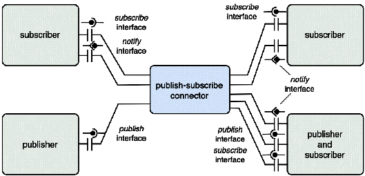
Coordination-based systems have been examined in Chapter 6 . Such a system may again be represented as a set of clients linked by a connector. Two typical examples are a mediation system, such as the one described in Chapter 1 , and a cooperative document edition system. In each case, a variant of the publish-subscribe communication paradigm is used. The minimal interface includes the synchronous publish and subscribe operations, and an asynchronous notify signal that is sent to subscribers when an event to which they subscribed occurs. A generic form of a coordination system is represented on Figure 7.4. Note that a client may act as a subscriber, as a publisher, or as both.
Chapters/Compo/Figs/pub-sub.gif
Figure 7.4: A coordination-based system
The coordination connector may encapsulate a variety of mechanisms, including a message bus or a system based on a shared workspace, examples of which include Linda or Jini.
Both the multimedia and the publish-subscribe system must accommodate a varying number of participants, which implies a mechanism for dynamic connection and disconnection. There are three possible approaches.
  1. creating a connector with a fixed number of interfaces of each type, thus setting an upper limit to the number of connections of each type.

  2. allowing a connector interface to be multiplexed between several participants.

  3. allowing dynamic creation of interfaces of a given type. For instance, if a new subscriber is admitted to the publish-subscribe system, a new subscriber interface is created.

Solution 1 is overly rigid. The other solutions raise the issue of multiplexing, which is done at different levels in solutions 2 and 3. Solution 3 combines architectural simplicity (one-to-one interfaces) and flexibility; see an example in 7.6.1.

7.3.4  Software Engineering Considerations

Up to now, we have examined the technical aspects of component-based software architecture. However, other points of view are equally important. In [Medvidovic et al. 2007], the authors define three "lampposts", or sources of insights, under which software architecture, and specially ADLs, may be examined. These are technology, domain, and business.
The technology approach is mainly guided by the tools and environments that may be supported by an ADL, specially as regards the relationships between a system's description and its implementation.
The domain approach takes into account the specific concerns, constraints and properties of a particular application domain. This approach has led to the development of domain-specific languages, and may be extended to architecture descriptions. The main difficulty is to capture in a rigorous notation the properties that characterize a domain, as the knowledge of these properties is part of the domain's specialists' experience and is not always explicitly expressed.
The business approach is concerned with organizational aspects of software development. These aspects include the product strategy (defining various product lines targeted to specific market segments, and how these products are mutually related), and the processes used by the software development organization to create, manage and evolve its products. Here again the difficulty lies in making these elements explicit, and in identifying which elements may be captured by a formal description such as provided by an ADL.
In conclusion of their analysis, [Medvidovic et al. 2007] argue that the next generation of ADLs should provide better support for the domain and business aspects, but that it is unlikely that such a wide range of concerns could be adequately captured by a single notation (even with multiple views such as provided by UML 2.0). Therefore a wide coverage should be best achieved using extension techniques.

7.4  Elements of a Component Model

Recall (7.1) that a component model defines specific standards for the various properties of a component, while a component framework provides the services needed to actually use component implementations conforming to the model supported by this framework. In this section, we attempt to identify those properties of an abstract component model that do not depend on a specific supporting framework. Since components cannot be used independently from a framework, such separation is not always easy. Framework-specific aspects are examined in Section 7.5.
There is currently no single universally accepted component model. In this presentation, we do not attempt to cover the various aspects of a model in their full generality. The main restrictions apply to the dynamic behavior of components; for instance, we assume that the type of a component (defined in 7.4.2) does not change during its lifetime, although some models allow the implementation of a component to be dynamically modified.
We examine the following points: naming and visibility (7.4.1); component lifecycle (7.4.4); component typing and conformance (7.4.2); component binding and configuration (7.4.3); component control (7.4.5).

7.4.1  Naming and Visibility

The general principles of naming (Chapter 3 ) apply to components. The basic notion is that of a naming context, an environment for name definition and resolution. Usually, a component Comp has a name name in a naming context NC in which it was created. Then, if ctx is a universal name of NC (i.e., a name valid in all contexts, such as an URL), ctx:name is a universal name for the component Comp (such a name is often called a reference for Comp).
One specific feature of naming for components is that a component may itself take the role of a naming context. In this context, external components may be designated by local shorthand names. These names are mapped to references using a local table. In addition, if the model allows composite components, the included components are also designated by local names. Included components may or may not be made visible from outside the composite component, according to the visibility rules define by the model. Components that are shared between several naming contexts have a name in each of these contexts, and these names are mapped to the single reference of the shared component.
A typical use of a naming context is to group a family of things that are related together, like in the above case of the internal components of a composite component. Other examples include Java packages (for components models based on Java) and OSGi bundles (7.7).

7.4.2  Component Typing and Conformance

In object models such as considered in Chapter 5 , there is a distinction between a class (a generic description) and instances of this class (objects that conform to this generic description). Likewise, we make a distinction between a "component template" (a generic description of a family of components) and individual component instances generated from this template. Contrary to objects, this distinction is not usually embodied in a programming language, at least in the current state of the art.
Still following the analogy with object models, we define a notion of type for a component (the type is associated with the template). The type is defined by the set of interface descriptions, both required and provided. Instances created from a template share the type of this template.
The notion of conformance defined for interfaces may be extended to components. In a configuration composed of a set of components, consider a single component, which is bound to the rest of the configuration through a set of required and provided interfaces. Each required interface Ir of the component is bound to a provided interface Sp of the configuration, while some or all provided interfaces Ip of the component are bound to a required interface Sr of the configuration. The following relations must hold for all provided and required interfaces of the component (recall that \sqsubseteq denotes the subtyping relation):
T(Ip) \sqsubseteq T(Sr) and T(Sp) \sqsubseteq T(Ir)
Any component may be substituted to the given component, as long as the above relations hold. Note that the substitute may have more provided interfaces (but no less required interfaces) than the original component.
Therefore the conformance relationship between two components C1 and C2 may be defined as follows:
C2 conforms to C1 (written T(C2) \sqsubseteq T(C1)) if the following conditions hold:
By definition of conformance, if T(C2) \sqsubseteq T(C1), then C2 (more precisely, any instance whose type is T(C2)) may be used in any place where an instance having type T(C1) is expected.
The definition of conformance may be extended to semantic aspects, if one can specify the behavior of a component in a formalism that allows equivalence to be defined, such as finite state machines.

7.4.3  Binding and Configuration

A configuration is an assembly of components. As said in 7.3.2, a configuration may be described by a notation (ADL) which specifies the components that form the configuration and their interconnection. Typically, an ADL contains statements of the form:
A.Required_interface is connected to B.Provided_interface
where A and B are components that are part of the configuration and are described by declarative statements in the ADL. Not all component systems, however, use an ADL, and the above statement is then implicit (i.e., it has to be inferred from the program of the components).
Actually producing a working configuration implies a binding phase, in which the connections between the components are created in the form of binding objects (or connectors). Depending on the component model and on its implementation, the binding may be static (preliminary to the execution) or dynamic (performed during execution, e.g., at first call), as explained in Chapter 3 .
Again depending on the component model, a configuration may or may not be itself a component. In the latter case, the configuration may be activated through a specified entry point (the equivalent of a main procedure), which is part of the provided interface of one of its components; there may be several such entry points. If a configuration is itself a (composite) component, then the interfaces of that component must be specified, using the interfaces of its contained components.
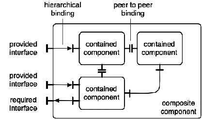
Chapters/Compo/Figs/compo-bindings.gif
Figure 7.5: Bindings in a composite component
As shown on Figure 7.5, there are two kinds of interface bindings in a composite component.
Both types of bindings are controlled by the manager of the composite component (7.4.5).
A final point regards multiple connections to an interface. As said in 7.3.3, one way of multiplexing an interface Int of a component is to dynamically create a new instance Intk of this interface at each binding of Int to another interface. Associating an execution unit (process or thread) with the new interface may be done by one of the methods described in 1.3.2 . Dynamic interface instantiation is done by the component manager.
This mechanism bears some analogy with the creation of sockets when a new client connects to a server socket, which may be considered as a low-level mechanism for dynamic interface instantiation (see 3.3.2 ). Note that dynamic interface instantiation is also applicable to required (client) interfaces.

7.4.4  Component Lifecycle

The lifecycle of a system describes its evolution from creation to deletion. We first consider the simple case of a single, primitive component. We then examine the problems posed by starting and stopping a configuration.
We only present a generic framework for defining the main lifecycle aspects of a component model. Existing component systems propose many variations and extensions of this scheme.

The Lifecycle of a Primitive Component

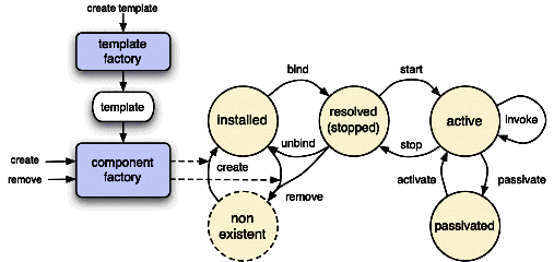
Creating instances of a primitive component described by a certain template may be done through a factory (2.3.2 ) associated with the template. The factory is associated with a naming context: it delivers a name in this context (a reference) for the newly created component. The factory may then act as a manager of the instances that it has created. It therefore supports lookup and remove operations, using component references as parameters. More elaborate lookup mechanisms using higher level names are usually available in component frameworks.
The template itself may be created by a template factory, using a description of the template's type (the set of its required and provided interfaces) and implementation.
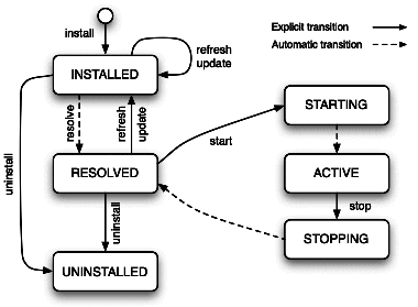
Once created, a component is installed, i.e., made accessible in the system through a reference. A component usually depends on other resources (e.g., services provided by the infrastructure or by other components. These dependencies must be resolved through a binding process (see 3.3 ), which may be static (before execution) or dynamic (at run time). A (partially) resolved component may then be activated. An active component may be used through its provided interfaces; it may be stopped (it then ceases all activity until restarted).
Chapters/Compo/Figs/lifecycle.gif
Figure 7.6: A component's lifecycle
Some component models (e.g., Enterprise JavaBeans) define a "passivated" state, in which the internal state of the component is frozen, and its representation is saved. A component may not be used while in passivated state. The motivation for component passivation is twofold5.
The state diagram of a component's lifecycle is represented on Figure 7.6.

Starting and Stopping a Configuration

The problem of starting and stopping a configuration, as opposed to a primitive component, is a complex one, because of the dependencies between components.
A component A directly depends on a component B if the correct execution of A relies on the correct execution of B. In terms of bindings, A directly depends on B if a client interface of A is bound to a server interface of B. More generally, the depends on relation is defined as the transitive closure of directly depends on.
When starting a configuration (an assemblage of components), the following invariant must be preserved: if component Ci depends on Cj, then Ci may only be started if Cj in the active state. Circular dependencies, if any, should be treated as a special case (e.g., by defining sub-states within a component, corresponding to the activation of different threads executing different operations). A configuration usually defines one or several entry points, i.e., methods in specific components to be called to start the configuration (the equivalent of a main() method in a C or Java application).
Stopping a configuration is more complex, since a component that is in the stopped state may be re-activated by a call from another, still active, component. To take this situation into account, one defines the notion of quiescence: a component is quiescent if (i) the component is stopped (no thread executes one of its methods), and its internal state is consistent; and (ii) it will remain stopped, i.e. no further calls to methods of this component will be issued by other components. The configuration is stopped when all its components are quiescent.
Quiescence detection is examined in 10.5.3  (about reconfiguration), since quiescence is also a prerequisite for dynamic reconfiguration. directly depends on.

7.4.5  Component Control

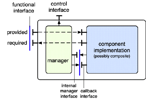
The notion of a component manager6, i.e., an entity that exercises control over a component or set of components, is present in all component models, under various forms. The main functions related to components are lifecycle management, binding, and interaction with other components. The role of a component manager is to perform these functions on behalf of a component, thus acting as a mediator between the component's internals and the outside world. The main motivation for this structure is separation of concerns: isolating the functions of the application proper from those related to execution mechanisms, to administration, or to the provision of extra-functional properties.
With this two-level organization, a component's manager screens all interactions of the component with other components and with the environment (e.g., system services). The interaction of a component with its manager (Figure 7.7) thus follows the pattern of inversion of control (2.1.1 ).
Chapters/Compo/Figs/manager.gif
Figure 7.7: Component-manager interaction
At this level of description, we do not make any assumption on the actual implementation of the manager. This aspect is examined in 7.5.
The following functions are provided by a component manager.
Additional framework-related functions (management of system services) are discussed in 7.5.

7.5  Patterns and Techniques for Component Frameworks

The function of a framework, or infrastructure, for components is to provide support for all the post-design phases of the life cycle of a component-based application: development, deployment, execution, administration and maintenance. In this section, we examine the organization of these infrastructures. Specific examples are developed in the following sections.

7.5.1  Functions of a Component Framework

A framework for component support must provide the following functions to the components that it manages.
  1. Support for lifecycle: creating, finding, passivating and activating, deleting instances of components. Additional framework-specific functions include pooling (managing virtual instances of components, see 7.5.3).

  2. Support for functional use, i.e., binding a component to other components, and using a component through its provided interfaces; this may include local as well as remote invocations.

  3. Support for the provision of extra-functional properties, as described in 7.2.2 (persistence, security, availability, QoS), and for the provision of system-managed services, such as transactions (7.2.2). The framework usually acts as a mediator to the providers of such services.

  4. Support for self-management of components and configurations. This includes adaptation and introspection (reflective capabilities); for composite components, this also includes managing included/shared components (7.4).

There is no standard terminology for component support frameworks. The most common notion is that of a container, defined as an environment for one or more component(s), which screens the components from the outside world by intercepting incoming and possibly outgoing calls, and acts as a mediator for the provision of common services. Due to historical reasons, the term "container" is often connoted as a heavyweight structure, although lightweight containers are common in recent frameworks such as Spring [Spring 2006], PicoContainer [PicoContainer ] and Excalibur [Excalibur ]. Some systems define their own terminology (e.g., component support in Fractal (7.6) is done by a set of controllers).
Two major qualities required from a component framework are adaptability and separation of concerns, which may be obtained using the techniques examined in Chapter 2 .
In the rest of this section, we develop different aspects of component framework design: using inversion of control to achieve separation of concerns (7.5.2); efficiently implementing the factory pattern (7.5.3); using interceptors (7.5.4) to control component interaction with the outside world; using reflection and aspects (7.5.5) to achieve framework adaptation.

7.5.2  Inversion of Control and Dependency Injection

The inversion of control pattern (2.1.1 ) is a basic construct of frameworks for component management. It appears in various forms, some of which are presented in this section. The common feature is that the initiative of a controlled operation resides with the framework, which calls an appropriate interface provided by the component. When recursively applied (i.e., a callback triggers another callback, possibly on a different component), this mechanism is extremely powerful.
The main purpose of inversion of control is to achieve separation of concerns (), by isolating the application proper from all decisions that are not directly relevant to its own logic. A typical example is the management of dependencies: when a component needs an externally provided resource or service for its correct execution, the identity of the resource or of the service provider is not directly relevant, as long as it satisfies its contract (2.1.3 ). Therefore this identity should be managed separately from the component's program, and interface-preserving changes should not impact this program.
One solution relies on a separate naming (or trading) service, using the BROKER pattern described in 3.3.4 . Dependent resources are designated by names (or by properties in the case of trading). This solution makes the application dependent on the (externally provided) naming or trading service. Requests to that service must be explicitly formulated. The alternative solution presented here relies on a configuration description to determine dependencies and to trigger the appropriate actions.
Dependency injection [Fowler 2004] is a pattern that applies inversion of control for the transparent management of dependencies. Although it is usually presented in the context of Java-based components, it has been applied to a variety of situations. Criteria of choice between a naming service (locator) and dependency injection are also discussed in [Fowler 2004].
The problem of dependency management is illustrated by the following simple example. An application consists of two components, compA and compB, defined by their types (i.e., set of interfaces), A and B respectively. compA uses the interface of compB (as defined by its type B). compB has an attribute v, whose initial value is a configuration parameter of the application.
Chapters/Compo/Figs/inversion-example.gif
Figure 7.8: Organization of a simple application
This (abstract) organization is shown on Figure 7.8a. Two concrete implementations (or configurations) are described on Figure 7.8b. In both Conf1 and Conf2, compA is an instance of an implementation AImpl of type A. In Conf1, compB is an instance of an implementation BImpl1 of type B, and the parameter v has value v1. In Conf2, compB is an instance b2 of an implementation BImpl2 of type B, and the parameter v has value v2. The abstract structure of the application is thus separated from configuration decisions. The goal is to preserve this separation in the actual implementation: changing from Conf1 to Conf2 should keep the application code invariant.
In [Fowler 2004], three forms of dependency injection are used to solve the dependency problem. We present them in turn, using the above example throughout.

Constructor Injection

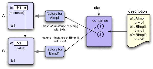
This form of injection uses factories. A factory (2.3.2 ) is a device that dynamically creates components of the same type. An example is the constructor of a Java class, which is used to create instances of that class, possibly with different initial values for its attributes.
Chapters/Compo/Figs/inversion-construct.gif
Figure 7.9: Inversion of control: constructor injection
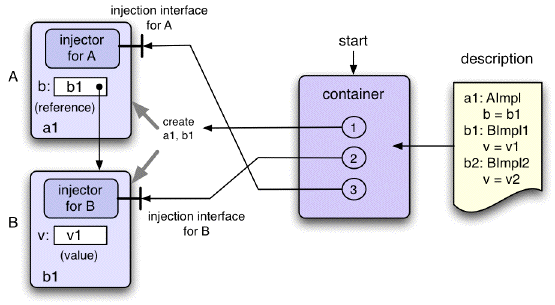
The mechanism used when starting the application is shown on Figure 7.9. The container calls in turn the appropriate factories for compA and compB, with the appropriate parameters ("appropriate" means as defined by the configuration), creating component instances called a1 and b1, respectively. The reference to compB in a1 has value b1, and the attribute v in b1 has value v1. In the organization shown, the program of the container uses a configuration description file; in that case, the container must determine the order in which the constructors should be called, by analyzing the configuration file to determine dependencies. Alternatively, the configuration parameters could be directly embedded in the program.
This pattern is used, among others, in Spring [Spring 2006] (a lightweight container framework for Java applications), as well as in the Enterprise Java Beans (EJB) 3.0. container [EJB ]. EJB is the component model and framework defined by the JEE standard [JEE ].
A form of constructor injection is also used in the configuration framework of Jonathan [Jonathan 2002]. In this solution, a configurator program is first generated from a configuration file, and executed at application startup.

Setter Injection

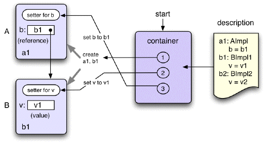
In setter injection, the process of creating a component is separated from that of setting its attributes. When a component is created by a factory, some or all of its attributes are uninitialized (or set to a default value such as NULL). Each attribute may then be initialized by calling the corresponding setter operation. The overall process is shown on Figure 7.10
Chapters/Compo/Figs/inversion-setter.gif
Figure 7.10: Inversion of control: setter injection
This pattern is also used in the above mentioned frameworks (Spring and EJB 3.0). The choice between constructor and setter injection is discussed in detail in [Fowler 2004]. Both mechanisms are useful in different situations, and may be combined. Constructors allow better encapsulation, since an attribute that is set in a constructor can be made immutable by not providing a setter for it. On the other hand, setters provide more flexibility, since some attributes may be set or modified after component construction. Setters may also be preferred if the number of attributes is large, in which case constructors become awkward.

Interface Injection

Interface injection is a more general solution than the two last ones. A new callback injection interface, tailored to each component type, is added to each managed component. The operations defined by this interface perform any needed initialization. Like in constructor injection, the order in which these operations are called may be determined from the configuration description or directly embedded into the program. The overall organization is shown on Figure 7.11
Chapters/Compo/Figs/inversion-inject.gif
Figure 7.11: Inversion of control: interface injection
As explained in [Fowler 2004], this process may be made more systematic by defining a generic injector interface, with a single operation inject(target), where target is the component being configured. This operation, in turn has a different implementation for each component, using the component-specific injectors. The injectors (code implementing the generic injector interface) may be included in the components (which must then export the generic injector interface), or directly in the container code. At system initialization, the container calls the injectors in an appropriate order, determined by analyzing the configuration description.

7.5.3  Factories

Component creation is done by a component factory (7.4.4). The implementation of a factory for container-managed components is often called a home. A container includes a home for each type of components that it manages.
As mentioned in 7.4.4, a component factory uses a form of component template, which may take different forms. The template may be explicitly created using a template factory, and it is used as an input by the component factory. Alternatively, the component factory may create predefined generic components, and use callback methods to initialize these components, as explained in 7.5.2.
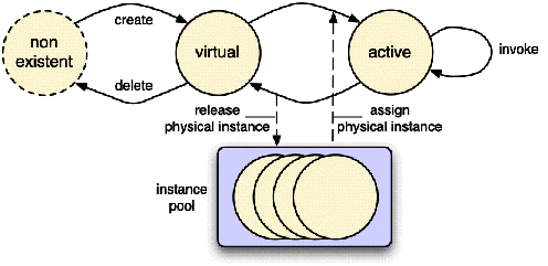
In order to reduce the overhead of creating and deleting component instances, containers often use instance pooling. Instance pooling is a technique for reusing component instances. The lifecycle diagram of Figure 7.6 is extended as shown on Figure 7.12 (the "stopped" and "passivated" states are not represented). The container maintains a pool of "physical" instances, which are not assigned to a specific component. A new instance of a component is created in a "virtual" state, in which it has no physical counterpart. At first invocation, a physical instance is taken from the pool and assigned to the virtual instance, which now may go to the active state. After some inactivity period (depending on the resource allocation policy), an active component may release the pooled physical instance and return to the virtual state. This technique is similar to paging in virtual memory systems, or to the management of concurrent activities by using a pool of threads.
Chapters/Compo/Figs/pooling.gif
Figure 7.12: Instance pooling
Note that instance pooling and passivation use similar techniques, but have different objectives. Instance pooling aims at reducing the number of component creations and deletions, while passivation aims at reducing memory occupation. In both cases, callback methods must be invoked in order to keep the component's state consistent (the state must be loaded when a component is assigned a pooled instance, and saved when the instance is released). This only applies to "stateful" components; nothing has to be done for "stateless" components. Examples are examined in the case studies.

7.5.4  Interceptors

A function of a container is to act as a mediator for its contained components: any (incoming or outgoing) communication of the component with the outside world is mediated by the container.
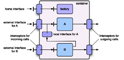
The technique used for this mediation function relies on interception (2.3.4 ). The container provides two objects associated with each of its contained components (Figure 7.13).
In order to reduce the cost of communication between components located in the same container, the container may also provide a local interface.
Chapters/Compo/Figs/container-intercept.gif
Figure 7.13: Container-mediated communication
An interface of a component must be bound prior to invocation. The binding works as follows.
A component's interface (let's say interface I of component C, denoted C.I) may be invoked by a thread running within a client or within another component. Prior to invocation, the calling thread must bind to the called interface, using a name to designate it. Two situations may occur.
To allow these bindings to be performed, a component must register its local and external interfaces in a local and a global registry, respectively.
Another use of interceptors is described in the next section.

7.5.5  Reflective Component Frameworks

As explained in 2.4 , reflective aspects have been introduced in middleware construction to deal with highly dynamic environments, for which run time adaptation is required. One approach is to integrate reflection in a component model and framework. Thus any software system, be it an application or a middleware infrastructure, built using reflective components, may benefit from their adaptation capabilities.
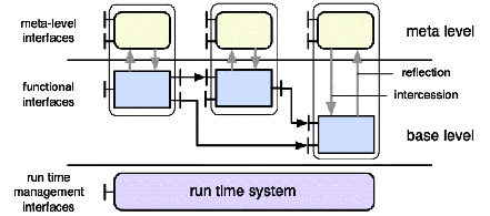
Recall that a reflective system is one that provides a representation of itself, in order to inspect or to modify its own state and behavior. This is usually achieved by defining a two-level organization (2.4.1 ): a base level, which implements the functionality of the system, and a meta level, which allows observing or modifying the behavior of the base level.
Chapters/Compo/Figs/reflection.gif
Figure 7.14: A reflective component system
This principle may be transposed as follows to a component framework. In addition to its functional interfaces, each component is equipped with one or several meta-level interfaces, which provide operations that allow inspecting or modifying the state or the behavior of the component. The meta-level programs cooperate with the run-time system to fulfill their function. Figure 7.14 gives a summary view of this organization.
In the rest of this section, we first discuss some implementation issues for reflective component frameworks. We next show how a reflective component framework can be used for system management.

Implementing a Reflective Component Framework

The main motivation for a reflective structure is adaptability, and this quality should apply to the meta-level itself. This might be achieved by adding a new reflection layer (meta-meta level), but this approach is usually considered overly complex and is seldom used.
The solution adopted by several systems is to implement the meta-level as a part of the component's manager (i.e., the software layer that acts as an environment for the components, as defined in 7.5.1), and to make the make the structure of the meta-level apparent, open, configurable, and extensible. This area is the subject of active research, and a number of experimental frameworks have been proposed. The solutions differ on the following points.
These techniques have been implemented both in heavyweight containers (such as the JBoss implementation [Fleury and Reverbel 2003] of J2EE), which uses both client-side and server-side interceptors), and lightweight component frameworks such as OpenCom [Clarke et al. 2001,Grace et al. 2006,Coulson et al. 2008], Fractal (7.6), DyMAC [Lagaisse and Joosen 2006]. Recent research [Pessemier et al. 2006a] aims at integrating components and aspects, by using aspects to implement the meta-level of a component framework, while representing aspects as components.
The insertion points at the base level (join points) are usually defined to be the incoming and outgoing calls, at a component's boundary, which respects the encapsulation principle by treating each component as a black box. However, it might be useful, in a limited number of cases, to define join points inside a component. This process (treating a component as a "grey box") needs to be carefully controlled since it breaks encapsulation: the internal join points must be explicitly specified in a special interface of the component. This technique has ben proposed in [Pessemier et al. 2006b], extending to components a similar proposal for "open modules" [Aldrich 2005].
Different framework implementations may be developed for a given component model. As an example, two frameworks for the Fractal component model are described in 7.6.2. One of them (AOKell) uses components and aspects to organize the meta-level, while the other one (Julia) uses non-componentized code with interceptors.

Using a Reflective Component Framework

The role of a reflective framework is to facilitate the dynamic adaptation of an application to a changing environment. Here are two examples.
Other examples include evolving a system to adapt it to changing user requirements.

7.6  Case Study 1: Fractal, a Model and Framework for Adaptable Components

Fractal [Bruneton et al. 2002,Bruneton et al. 2006] is a software composition framework, based on an original component model, that has been designed to answer the requirements presented in 7.2, with the following goals.
Fractal is not a product, but an abstract framework that can be used as a basis for a family of concrete frameworks complying with the Fractal model. Several implementations of the model are available (7.6.2).
Fractal was developed as a joint effort of France Telecom R&D and INRIA, and is an ongoing project of the ObjectWeb consortium (http://fractal.objectweb.org/).

7.6.1  The Fractal Model

This section presents the main elements of the Fractal model: components, interfaces and types, bindings, control and runtime management.

Components, Interfaces, and Bindings

A Fractal component consists of two parts: a membrane and a content. The membrane provides control facilities, while the content implements the component's functionality. The Fractal model defines two kinds of components: primitive and composite. A primitive (non decomposable) component may be used as a unit of application development, or as a means of encapsulating legacy code, making its interfaces visible and allowing it to be integrated into an application together with other components. A composite component encapsulates a set of components, primitive or composite. Thus a complex application (which is a composite component) has the same structure as any of its parts, hence the name "Fractal".
A component, be it primitive or composite, has three kinds of interfaces.
These are external interfaces, i.e., they are visible from outside the component. In addition, composite components have internal interfaces that are used to make visible some interfaces of their contained components. Such an internal interface is paired with an external interface of a complementary kind (i.e., the pairs are client-server or server-client). These interface pairs may be seen as channels across the composite component's membrane.
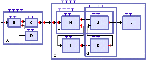
These notions are illustrated in the example shown on Figure 7.15, in which the membrane of a component is represented by the border frame that surrounds it, and the interfaces are represented using the notations described above. The composite component E contains two primitive components (I and L) and two composite components (F and G). F contains H and J, G contains J and K. J is shared between F and G.
Chapters/Compo/Figs/fractal-comp.gif
Figure 7.15: Composition and sharing in Fractal
The figure shows the two main mechanisms provided by Fractal to define a complex architecture: composition and binding. Client interfaces are bound to server interfaces; also note the interface pairs used to make visible the interfaces of contained components. The bindings involving control interfaces have not been represented; control mechanisms are described later in this section.
Two mechanisms may be used for bindings (see also 3.3 ). If the bound interfaces are in the same address space (primitive binding), the binding is represented by the equivalent of an address (e.g., a pointer, a Java reference). If the bound interfaces are in different address spaces (composite binding), the binding is embodied in a binding object (or connector) which itself takes the form of a component. As said in 7.3.1, there is no structural difference between a connector and a (possibly composite) component. Distributed applications, involving proxies and communication protocols, can be constructed in this fashion.
An original feature of Fractal is the ability to share components between composite components. This allows the shared component's state to be itself shared between the enclosing components. The alternative to sharing would be either to replicate the component, which entails consistency maintenance, or to keep the component outside the sharing composite components, which complexifies the application's structure and defeats the purpose of encapsulation. Shared components are a convenient way of representing shared stateful resources; they are also useful when the component structure is used to represent management or protection domains (see 10.1.2 ). The behavior of a shared component is defined by the control part of the smallest component containing all its enclosing composite components (e.g., in the example of Figure 7.15, the behavior of J is controlled by E).

Component Control

The function of controlling a component is devoted to its membrane, which is composed of an arbitrary number of controllers, each in charge of a specific function. The membrane acts as a meta-level in a reflective architecture (2.4.1 , 7.5.5), and provides introspection and intercession operations with respect to the component's content. To do so, the membrane maintains a causally connected representation of the component's content.
The Fractal model does not impose the presence of any pre-determined set of controllers, but defines several levels corresponding to an increasing degree of control.
At the lowest level, no control facilities are provided. This is the case of components that encapsulate legacy software for which no control "hooks" are available. The only mandatory interface other than the functional ones is the Naming interface (see 3.4.2 ): a component is a naming context, in which its interfaces have local names. Thus if a component has name Comp in some enclosing context (e.g., a directory, or a virtual machine), its interfaces may have such names as Comp.Int1, Comp.Int2, etc. This ensures name isolation, as different interfaces may have the same name in different components.
The next level of control provides external introspection capabilities, in the form of two interfaces, Component and Interface, which allow the discovery of all interfaces (both internal and external) owned by the component7.
The upper levels of control include both introspection and intercession facilities. The most usual controllers defined by the Fractal specification are the following.
In addition, since the Fractal model is open, customized controllers may be added for specific purposes. Thus, for example, components may be enhanced with autonomic management facilities (), as has been done in the Jade system [Bouchenak et al. 2006] based on Fractal.

Components' Lifecycle

Lifecycle covers two aspects: component instantiation and removal, and execution control. Note that the Lifecycle controller only deals with the second aspect.
Components are created using factories. For a language-specific implementation of the Fractal platform, these factories may be directly implemented using the specific creation mechanisms of the supported language (e.g., new for Java, etc.). In addition, the available frameworks provide more convenient mechanisms, based on templates (a template is a specialized factory for a given component type; a template is itself created using a generic factory). This process may itself be activated by interpreting ADL constructs, and is thus made invisible to developers. Once created, the components must be bound to compose applications. This again may be done directly, using binding controllers, or by interpreting ADL sequences.
A component may be removed from the content of an enclosing component via the removeFcSubComponent operation of the ContentController interface.
Execution control is done via three operations provided by the LifecycleController interface: getFcState returns the current state of a component (stopped or started), while startFc and stopFc trigger state transitions. The semantics of these operations has been voluntarily left as weak as possible; these operations are usually extended or redefined to suit specific applications' needs.

Types and Conformance

In Fractal, interfaces and components are optionally typed. An interface type comprises the following elements.
A component type is a collection of interface types, which describe the interfaces that components of this type may or must have at run time (depending on their contingency).
The usual notion of interface conformance, as defined in 2.1.3 , applies to Fractal interfaces types, but must be extended to take contingency and cardinality into account. Interface type IT2 conforms to Interface type IT1 (noted IT2 \sqsubseteqF IT1)9 if any instance it1 of IT1 can be replaced by an instance it2 of IT2. This requires the following conditions to be met.
The notion of component conformance (or substitutability) follows (see 7.4.2). Let CT1 and CT2 be component types (collections of interface types). Then CT2 \sqsubseteq CT1 iff:

7.6.2  Fractal Implementation Frameworks

Since most elements of the Fractal specification are optional, an implementation of this specification is best conceived as an extensible framework, whose main function is to allow the programming of component membranes.
Several Fractal implementation frameworks have been developed. They differ by the target language (implementations exist for C, C++, Java, and Smalltalk), by the techniques used, and by the additional capabilities provided. In the rest of this section, we briefly describe two such frameworks, Julia and AOKell. Other frameworks include Think [Fassino et al. 2002], designed for operating systems kernels, using the C language, and ProActive [Baduel et al. 2006], designed for active, multithreaded Java components in a grid environment.

The Julia Framework

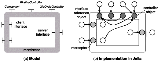
Julia [Bruneton et al. 2006] is the reference implementation of the Fractal component model. It is based on Java and provides a set of tools for the construction of component membranes. In addition to the objects that implement the component's contents, two kinds of Java objects are used:
This is illustrated by Figure 7.16. Controller objects are represented in dark gray, interceptors in light gray, and interface references in white.
Chapters/Compo/Figs/julia.gif
Figure 7.16: Controllers and interceptors in the Julia framework
Since the different control operations may be related to each other, controllers and interceptors usually contain mutual references. Controllers and interceptors are generated by factories, which take as input a description of the functional and control parts of the components.
Controllers are required to be flexible (to cater for a variety of levels of control) and extensible (to allow user-defined extensions). The construction framework must comply with these requirements. This is done by providing a basic implementation for each controller, which may be extended through the use of mixin classes. This method was preferred to class inheritance, which would lead to code duplication, in the absence of multiple inheritance10. Mixin classes allow a method of a base class to be extended by adding code fragments at specified locations, or to be overridden with a new method. Several mixins may be applied to a given base class; the order of application is significant. For efficiency, the mixed classes are dynamically generated in byte-code form.
In the Julia framework, controllers implement the generic (i.e., common to all methods) part of component control. The method-dependent parts, when needed, are implemented by interceptors (2.3.4 ), which insert code fragments before and/or after an incoming or outgoing method call. In a similar way to controller generation, this additional code may be dynamically inserted in byte-code form. The code insertion mechanism is open and extensible.
Julia provides various optimization mechanisms, whose effect is (a) to merge the various code pieces that make up a component's membrane into a single Java object; and (b) to shorten the chain of indirect calls (through reference objects and interceptors) that makes up an inter-component method call.
Julia has been used to develop various Fractal-based systems, one of which is the Dream communication middleware framework, described in . Experience reported in [Bruneton et al. 2006] shows that the additional flexibility brought by the use of configurable components is paid by a time and space overhead of the order of a few per cent.

The AOKell Framework

Like Julia, the AOKell component framework [Seinturier et al. 2006] is a complete implementation of the Fractal specification. It differs from Julia on two main points: control functions are integrated into components using aspects (2.4.2 ), and the controllers are themselves implemented as components. The objective of this organization is to improve the flexibility of the control part of the components, by making its structure open, explicit, and easily adaptable.
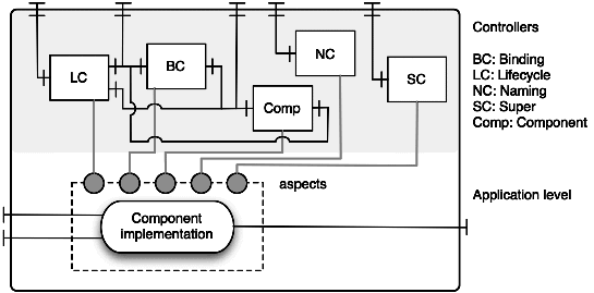
In AOKell, the membrane of a Fractal component is a composite component enclosing a set of interacting components, each of which performs the function of a particular Fractal controller. The membrane may be seen as a meta-level layer (2.4.1 ), sitting above the base layer that provides the functional behavior of the component. However, this reflective structure does not extend further up: the controllers that make up the membrane are Fractal components equipped with a predefined membrane.
Chapters/Compo/Figs/aokell.gif
Figure 7.17: A primitive component's membrane in the AOKell framework
The controllers interact with the base level through aspects (2.4.2 ): each controller is in charge of a specific function, and is associated with an aspect that is used to integrate that function into the component's base layer (the component's functional part). This is done using two mechanisms provided by the AspectJ extension to Java (2.4.2 ):
The membrane has a different structure for primitive and for composite components (in particular, the former do not have a content controller). The overall organization of a primitive component is described on Figure 7.17.
A component's membrane may be easily extended with additional controllers. For instance, a logging controller may be added, e.g., to log method calls. This may be done for a specific component, or for a whole set of components by defining a new membrane template including the logging controller.
The overall performance of AOKell is comparable to that of Julia within a 10% margin (AOKell is more efficient with injection, less efficient with interception).

7.6.3  Fractal ADL

The Fractal Architecture Description Language (Fractal ADL) is an extensible formalism to describe the global architecture of a system built out of Fractal components. It is associated with an extensible set of tools that may perform various tasks such as code generation, deployment, analysis, etc.
The Fractal ADL and its associated tool-set are open, in the sense that they are not tied to a particular implementation language, nor to a specific step in the software's lifecycle.

The description language

A description in Fractal ADL is organized as a set of XML modules, each associated with a DTD (Document Type Definition) that defines its structure. This modular structure is designed for extensibility: to introduce a new aspect in the description, one needs to provide the corresponding DTD. Thus, in addition to the basic aspects (interfaces, bindings, attributes, containment relationships), a number of additional aspects can be introduced, such as typing, implementation properties, deployment, QoS contracts, logging, etc.
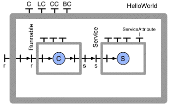
A simple example, taken from the Fractal tutorial [Fractal ] gives a flavor of the form of the core Fractal ADL. The HelloWorld application is organized as a composite component, which contains two primitive components, Runnable and Service. Service exports an interface s used by Runnable, which in turn exports an interface r re-exported by the HelloWorld component. This organization is summarized on Figure 7.18.
Chapters/Compo/Figs/hello-world.gif
Figure 7.18: A simple Fractal application (from [Fractal ])
This application is described by the following Fractal ADL fragment
<?xml version="1.0" encoding="ISO-8859-1" ?>
<!DOCTYPE definition PUBLIC
    "-//objectweb.org//DTD Fractal ADL 2.0//EN"
    "classpath://org/objectweb/fractal/adl/xml/basic.dtd">

<definition name="HelloWorld">
  <interface name="r" role="server" signature="java.lang.Runnable"/>
  <component name="client" definition="ClientImpl"/>
  <component name="server" definition="ServerImpl"/>
  <binding client="this.r" server="client.r"/>
  <binding client="client.s" server="server.s"/>
</definition>

This fragment specifies the HelloWorld component in terms of its contained components, whose definitions follow (XML headers are omitted from here on):
<definition name="ClientImpl">
  <interface name="r" role="server" signature="java.lang.Runnable"/>
  <interface name="s" role="client" signature="Service"/>
  <content class="ClientImpl"/>
</definition>

<definition name="ServerImpl">
  <interface name="s" role="server" signature="Service"/>
  <content class="ServerImpl"/>
</definition>

The names of the implementation classes are the same as the names of the definitions. This is only a convention, not a necessity.
These definitions could in fact be embedded into the description of the HelloWorld component, which would make the overall description more concise; however, in that case, the descriptions of the contained components could not be reused.
The controller of a primitive or composite component may be specified by defining a controller descriptor, as well as an attribute controller interface, and attribute values:
<definition name="ServerImpl">
  <interface name="s" role="server" signature="Service"/>
  <content class="ServerImpl"/>
  <attributes signature="ServiceAttributes">
    <attribute name="header" value="->"/>
    <attribute name="count" value="1"/>
  </attributes>
  <controller desc="primitive"/>
</definition>

Component types may be defined, which allows using inheritance, by adding new clauses to an existing type:
<definition name="ClientType">
  <interface name="r" role="server" signature="java.lang.Runnable"/>
  <interface name="s" role="client" signature="Service"/>
</definition>

<definition name="ClientImpl" extends="ClientType">
  <content class="ClientImpl"/>
</definition>

The above definition of ClientImpl is equivalent to that previously given. New clauses can also override existing ones.
Other aspects of the Fractal ADL may be found in the tutorial [Fractal ].

The Fractal ADL tool-set

The first set of tools using the Fractal ADL are factories used to instantiate a configuration from its ADL description. Thus, using the HelloWorld example, the following sequence instantiates a ClientImpl component:
Factory f = FactoryFactory.getFactory();
Object c = f.newComponent("ClientImpl", null);

Here Factory and FactoryFactory are provided in the Fractal distribution. The second argument of the newComponent method may be used to specify additional properties. The component creation proper is done by a back-end component, which comes in several versions (using either the Java reflection package or the API provided by the Fractal framework for component creation).
Another use of the Fractal ADL is as a pivot language for various tools. In particular, the ADL serves as a support for a graphical interface that provides a graphical view of a Fractal configuration, which can be directly manipulated by the users.
As a final illustration of the association between tool-sets and architectural system descriptions, we briefly describe the design of an extensible tool-set [Leclercq et al. 2007] initially developed with Fractal ADL as a support language, but potentially usable by other ADLs. The tool-set is operated as a workflow, made up of three main components.
  • The loader reads a set of input files (typically ADL descriptions) and generates an abstract syntactic tree (AST), using grammars and parsers for each input language. The AST represents the structure of a system in an extensible, language independent form. Each node represents an element of the system under description (e.g., components, interfaces, methods, etc.), and has an extensible set of interfaces (e.g., to retrieve its properties or to give access to its children).

  • The organizer processes the AST to generate a graph of tasks to be executed (e.g., creating component instances, creating bindings between components, etc.).

  • The scheduler determines the dependencies between the tasks in the graph, and schedules the execution of the tasks in an order that respects these dependencies.

The tool-set support the following services: verification of the architecture's correctness (e.g., correct binding of the interfaces, including type-checking); generation of "glue code" for components; generation of stubs and skeletons for distributed components; compilation of source code and instantiation of components. This range of services is easily extensible, thanks to the modular structure of the tool-set and to the extensibility of the AST format. More details may be found in [Leclercq et al. 2007].
  
In conclusion, the main features of the Fractal ADL are its modularity, its extensibility, and its use as a pivot format for a variety of tools. Dynamic extensions are the subject of current research.

7.7  Case Study 2: OSGi, a Dynamic, Component-Based, Service Platform

The OSGi Alliance [OSGI Alliance 2005], founded in 1999, is an independent non-profit corporation that groups vendors and users of networked services. Its goal is to develop specifications and reference implementations for a platform for interoperable, component-based, applications and services.
The OSGi specification defines both a component model and a run time framework, targeted at Java applications ranging from high-end servers to mobile and embedded devices. OSGi components are called bundles. A bundle is a modular unit composed of Java classes, which exports services, and may import services from other bundles running on the same Java Virtual machine (JVM). A service is typically implemented by a Java class provided by a bundle, and is accessible through one or several interfaces. In addition, a service may be associated with a set of properties, which allow services to be dynamically published and searched, using a service discovery service (3.2.3 ) provided by the framework.
In the rest of this section, we briefly summarize the main aspects of the OSGi specification, and we show how it is used to develop service-based applications. We conclude with a review of some implementations and extensions.

7.7.1  The OSGi Component Model

An OSGi bundle is a unit of packaging and deployment, composed of Java classes and other resources such as configuration files, images, or native (i.e., processor-dependent) libraries. A bundle is organized as a Java Archive (JAR) file11, containing Java classes and other resources, together with a manifest file, which describes the contents of the JAR file and provides information about the bundle's dependencies (i.e., the resources needed for running the bundle).
The unit of code sharing between bundles is a Java package. A bundle can export and import packages12. Exported packages are made available to other bundles, while imported packages are taken from those exported by other bundles. If the same package is exported by several bundles, a single instance is selected (the one exported by the bundle with the highest version number, and the oldest installation date). Packages that are neither imported nor exported are local to the bundle.
Package sharing between bundles takes place within a JVM and relies on the class loading mechanism of Java. Each bundle has a single class loader. The class space of a bundle is the set of classes visible from its class loader, through class loading delegation links; it includes, among others, the imported packages and the required bundles specified by the bundle. Thus the OSGi framework supports multiple class spaces, which allows multiple versions of the same class to be in use at the same time.
In terms of the Fractal component model, OSGI bundles may be seen as having the equivalent of a binding controller and a lifecycle controller. A bundle's lifecycle is represented on Figure 7.19. The states and transitions are summarized as follows.
Installation  
Installation is the process of loading the JAR file that represents the bundle into the framework. The bundle must be valid, i.e., its contents must be consistent and error-free. A unique identifier is returned for the installed bundle. The installation process is both persistent (the bundle remains in the INSTALLED state until explicitly un-installed) and atomic (if the installation fails, the framework remains in the state in which it was prior to this operation).
Resolution  
An installed bundle may enter the RESOLVED state when all its dependencies, as specified in its manifest, are satisfied. Resolution is a binding process, in which each package declared as imported is bound (or "wired", in the OSGi terminology) to an exported package of a RESOLVED bundle, while respecting specified constraints. These constraints take the form of matching attributes, e.g., version number range, symbolic name, etc. Resolution of a bundle is delayed until the last possible moment, i.e., until another bundle requires a package exported by that bundle.
Chapters/Compo/Figs/bundle-life.gif
Figure 7.19: The lifecycle of an OSGI bundle (from [OSGI Alliance 2005])
Imported packages may be specified as mandatory (the default case), optional, or dynamic. Mandatory imports must be satisfied during the resolution process. Optional imports do not prevent resolution if no matching export is found. Dynamic imports may wait until execution time to be resolved.
After a bundle is resolved, the framework creates a class loader for the bundle.
Activation  
Once in the RESOLVED state, a bundle may be activated. The bundle's manifest must specify a Bundle-Activator class, which implements the predefined BundleActivator interface. This interface includes two methods, start and stop. When a bundle is activated, the framework creates an instance of Bundle-Activator and invokes the start(BundleContext) method on this instance, where BundleContext represents the current context of the bundle. The context is an object that contains the API of the OSGi framework, as well as specific parameters. The start method may look for required services (see 7.7.2), register services, and start new threads if needed. If the method succeeds, the bundle enters the ACTIVE state. If it fails, the bundle returns to the RESOLVED state. The STARTING state is the transient state of the bundle during the execution of the start(BundleContext) method.
Stopping  
An active bundle may be stopped by invoking the stop(BundleContext) method of its Bundle-Activator class instance. This method must unregister the provided services (see 7.7.2), release any required services, and stop all active threads. The bundle returns to the RESOLVED state. The bundle is in the transient STOPPING state while the stop method is executing.
Update  
A bundle may be updated (i.e., modified to produce a new version). If the bundle is active, it is first stopped. The framework then attempts to reinstall and to resolve the bundle. Since the update may change the list of imported and exported packages, resolution may fail. In that case, the bundle returns to the INSTALLED state and its class loader is removed.
Un-installation  
Un-installing a bundle moves it to the UNINSTALLED state (a terminal state, from which no further transition is possible). The JAR files of the bundle are removed from the local file system. If the bundle was in the RESOLVED state, those of its classes that were imported remain present as long as the importing bundles are in the ACTIVE state. The refresh operation restores a new consistent system after some bundles have been un-installed: it stops, resolves again, and restarts the affected (dependent) bundles.

7.7.2  Dynamic Service Management in OSGi

OSGi implements a service-oriented architecture [Bieber and Carpenter 2002], based on the modular infrastructure provided by bundles. A service (2.1 ) is accessible through one or more Java interface(s), and implemented by a Java class exported by a bundle. The OSGi service architecture is dynamic, i.e., services may appear or disappear at any time. An event-based cooperation model allows clients of services to be aware of this dynamic behavior in order to keep applications running.
Service management is based on a (centralized) service registry provided by the OSGi framework, together with an API allowing users to register and to discover services. To facilitate discovery, a service is registered with one or more interface name(s) and a set of properties. Properties have the form of key-value pairs, allowing the use of LDAP-style [LDAP 2006] filter predicates. Following the service usage pattern described in 3.3.4 , a client bundle can discover a service, get a reference for it, bind to the service, and invoke the methods specified by the service interface. When the client stops using the service, it should release it, which decrements the service reference count. When the count reaches zero, the providing bundle may be be stopped, and unreferenced objects may be garbage-collected.
Events are triggered when a service is registered or unregistered, and when properties of a registered service are modified. The OSGi framework provides interfaces to observe these events and to react to them, both in a synchronous and an asynchronous mode. In addition, the framework provides a ServiceTracker utility class, which allows a client to subscribe to events related to a specific service or set of services, and to activate appropriate handlers for these events.
The Service Component Runtime (SCR) defines a component model that facilitates the management of an application as a set of interdependent services. In this model, a declarative description, in the XML format, is associated with each bundle that provides or uses a service, and lists the dependencies of that service, i.e., the mandatory or optional services needed for its operation, and the callback handlers associated with various events. This description is used by the runtime to automatically manage the execution of the application, by activating the appropriate service registering and unregistering operations, which in turn trigger the corresponding callbacks.

7.7.3  OSGi Standard Services, Implementations and Extensions

A number of standard services have been specified by the OSGi Alliance. Some of them are generic, while others address a specific application domain. Examples of generic services are the HTTP service, which allows OSGi bundles to publish an application including both static and dynamic web pages; the Wire Admin service, which allows building sensor-based services, linking producers of measurement data to consumers; and the Universal Plug and Play (UPnP) Device Driver, which is used to develop UPnP-based applications [UPnP ] over an OSGI platform.
The OSGi specifications have been implemented by several commercial vendors. Several open-source implementations are also available: Knopflerfish [Knopflerfish 2007], Oscar [Oscar 2005], Felix [Felix 2007]. On the server side, the OSGi standard has also been adopted by the Eclipse project [Gruber et al. 2005], and by several projects of the Apache Foundation.
The current OSGI specification defines a centralized framework, in which the bundles that compose an application are loaded in a single JVM. We briefly describe R-OSGi [Rellermeyer et al. 2007], an experimental extension of OSGi to a distributed environment.
R-OSGI is an infrastructure for building distributed OSGi applications. Services are units of distribution, and interact through proxies (2.3.1 ). Proxies allow remote interactions between OSGi frameworks located at different sites; they have two main uses: remote service invocation and event forwarding.
Service distribution in R-OSGi is transparent, i.e., a remote service is functionally equivalent to a local service (except of course for distribution-aware functions such as system management). Transparency is achieved using the following techniques:
  • Dynamic proxy generation at bind time (i.e. when a client needs to bind to a remote service). The proxy is generated, as usual, from the service's interface description.

  • Providing a distributed Service Registry. When a service allowing remote access is registered in a local framework, R-OSGi registers it with a remote service discovery layer, which is based on SLP (3.2.3 ).

  • Mapping network and remote failures to local events (such as service removal), which applications running on a centralized OSGi framework are already prepared to handle.

  • Using type injection to resolve distributed type systems dependencies. The problem arises when the interface of a remote service contain parameter types that are not available at the client site (because they do note belong to the standard Java classes). Types present in interfaces and present in exported bundles are collected when a remote service is registered, and transmitted to the client at proxy generation time.

The performance of R-OSGi for remote service invocations has been found slightly better than that of Java RMI (5.4 ).

7.8  Historical Note

As recalled in the Introduction, the vision of software being produced by assembling "off the shelf" software components [McIlroy 1968] dates from the early years of software engineering. This vision was first embodied in the notion of a module as a unit of composition; a module is a piece of program that can be independently designed and implemented, in the sense that it only relies on the specification of the modules it uses, not on their implementation. Seminal papers in this area are [Parnas 1972], which identifies decomposition criteria based on the "information hiding" principle (a form of encapsulation), and [DeRemer and Kron 1976], which introduces a first approach to software architecture description in the form of a Module Interconnection Language (MIL). A few programming languages include a notion of module (e.g., Mesa [Mitchell et al. 1978], Modula 2 [Wirth 1985], Ada [Ichbiah et al. 1986]), but none provides any construct for expressing global composition. Several experimental MILs were proposed (e.g., Conic [Magee et al. 1989], Jasmine [Marzullo and Wiebe 1987]), but none has achieved widespread use.
A further step in the definition of composition units was the advent of objects, which introduced the notions of classes and instances, inheritance and polymorphism. Early object-oriented languages are Simula 67 [Dahl et al. 1968] and Smalltalk 80 [Goldberg and Robson 1983]. However, objects did not bring new concepts in global architectural description. Distributed objects (see a brief historical review in Section 1.5 ) provided building blocks for the first middleware products, which appeared in the early 1990s.
Architectural concerns were revived in the early and mid-1990s (see [Shaw and Garlan 1996]), with further progress in the understanding of the notions of component, connector, and configuration. Based on these notions, the concept of an Architecture Description Language (ADL) was proposed as a way of expressing global composition. A number of proposals were put forward, both for component models (e.g., Fractal [Bruneton et al. 2006], Koala [van Ommering et al. 2000]) and for ADLs (e.g., Darwin [Magee et al. 1995], Wright [Allen 1997], Rapide [Luckham and Vera 1995], Acme [Garlan et al. 2000]). An attempt towards unifying global architectural description with component implementation is ArchJava [Aldrich et al. 2002], an extension of the Java programming language. An attempt towards a taxonomy of component models may be found in [Lau and Wang 2007].
Research on the theoretical foundations of component models has been going on since the 1990s, but no universally accepted formal model has yet been proposed. A collection of articles describing early work may be found in [Leavens and Sitaraman 2000]. More recent work is presented in [Lau et al. 2006], [Bidinger and Stefani 2003] (the latter gives a formal base for the Fractal component model (7.6)).
Component-based commercial platforms (JEE [J2EE ], .NET [.NET ]) appeared in the late 1990s and early 2000s, introducing components in the world of applications. Several container-based frameworks relying on inversion of control (7.5.2) have also been developed (e.g., Spring [Spring 2006], Excalibur [Excalibur ], PicoContainer[PicoContainer ]). Contrary to JEE and .NET, these frameworks do not assume a specific component format, and directly support Java objects13.
In the same period, several groups were investigating the use of "component toolkits" to build configurable operating systems kernels. Projects in this area include OSKit/Knit [Ford et al. 1997,Reid et al. 2000], Pebble [Gabber et al. 1999], Think [Fassino et al. 2002], CAmkES [Kuz et al. 2007]. The growing use of embedded systems should foster further proposals in this area.
The development of Service Oriented Architectures (SOA, see 2.1 ) puts emphasis on applications built out of dynamically evolving, loosely coupled elements. The OSGi service platform (7.7 and [OSGI Alliance 2005]), initially targeted at small devices, allows dynamic service composition and deployment on a wide range of infrastructures. Recent research on ADLs concentrates on extensible ADLs (e.g., xADL [Dashofy et al. 2005], the Fractal ADL (7.6.3)), and on dynamic aspects of ADLs.
In the late 1990s, it was recognized that the areas of software architecture, configuration management, and configurable distributed systems were based on a common ground [van der Hoek et al. 1998]. Configuration management (see 10.4 ) is emerging as a key issue, and a respectable subject for research. The advent of mobile and ubiquitous systems emphasizes the need for dynamic reconfiguration capabilities (see 10.5 ). A better understanding of the fundamental concepts of composition is needed to make deployment and (re)configuration reliable and safe. Active research is ongoing is this area, but its impact on current industrial practice is still limited.

References

[Aldrich 2005]
Aldrich, J. (2005). Open Modules: Modular Reasoning about Advice. In Proceedings of the 19th European Conference on Object-Oriented Programming, Glasgow, UK, number 3586 in Lecture Notes in Computer Science, pages 144-168. Springer-Verlag.
[Aldrich et al. 2002]
Aldrich, J., Chambers, C., and Notkin, D. (2002). ArchJava: connecting software architecture to implementation. In Proceedings of the 24th International Conference on Software Engineering (ICSE'02), pages 187-197, Orlando, FL, USA.
[Allen 1997]
Allen, R. (1997). A Formal Approach to Software Architecture. PhD thesis, Carnegie Mellon, School of Computer Science. Issued as CMU Technical Report CMU-CS-97-144.
[Baduel et al. 2006]
Baduel, L., Baude, F., Caromel, D., Contes, A., Huet, F., Morel, M., and Quilici, R. (2006). Grid Computing: Software Environments and Tools, chapter "Programming, Deploying, Composing for the Grid". Springer-Verlag.
[Bernardo et al. 2002]
Bernardo, M., Ciancarini, P., and Donatiello, L. (2002). Architecting Families of Software Systems with Process Algebras. ACM Transactions on Software Engineering and Methodology, 11(4):386-426.
[Bidinger and Stefani 2003]
Bidinger, Ph. and Stefani, J.-B. (2003). The Kell calculus: operational semantics and type system. In Proceedings of the 6th IFIP International Conference on Formal Methods for Open Object-based Distributed Systems (FMOODS 03), Paris, France.
[Bieber and Carpenter 2002]
Bieber, G. and Carpenter, J. (2002). Introduction to Service-Oriented Programming. http://www.openwings.org.
[Blair and Stefani 1997]
Blair, G. and Stefani, J.-B. (1997). Open Distributed Processing and Multimedia. Addison-Wesley. 452 pp.
[Bouchenak et al. 2006]
Bouchenak, S., De Palma, N., Hagimont, D., and Taton, C. (2006). Autonomic management of clustered applications. In IEEE International Conference on Cluster Computing, Barcelona, Spain.
[Bruneton et al. 2006]
Bruneton, É., Coupaye, T., Leclercq, M., Quéma, V., and Stefani, J.-B. (2006). The Fractal Component Model and its Support in Java. Software-Practice and Experience, 36(11-12):1257-1284. special issue on "Experiences with Auto-adaptive and Reconfigurable Systems".
[Bruneton et al. 2002]
Bruneton, É., Coupaye, T., and Stefani, J.-B. (2002). Recursive and dynamic software composition with sharing. In Proceedings of the 7th ECOOP International Workshop on Component-Oriented Programming (WCOP'02), Malaga (Spain).
[CCM ]
CCM. The CORBA Component Model. Object Management Group Specification. http://www.omg.org/technology/documents/formal/components.htm.
[Chan and Chuang 2003]
Chan, A. T. S. and Chuang, S.-N. (2003). MobiPADs: a reflective middleware for context-aware mobile computing. IEEE Transactions on Software Engineering, 29(12):1072-1085.
[Clarke et al. 2001]
Clarke, M., Blair, G. S., Coulson, G., and Parlavantzas, N. (2001). An Efficient Component Model for the Construction of Adaptive Middleware. In Middleware '01: Proceedings of the IFIP/ACM International Conference on Distributed Systems Platforms, Heidelberg, LNCS 2218, pages 160-178. Springer-Verlag.
[Coulson et al. 2008]
Coulson, G., Blair, G., Grace, P., Taiani, F., Joolia, A., Lee, K., Ueyama, J., and Sivaharan, T. (2008). A generic component model for building systems software. ACM Transactions on Computer Systems, 26(1):1-42.
[Dahl et al. 1968]
Dahl, O., Myhrhaug, B., and Nygaard, K. (1968). Simula 67 - Common Base Language. Norwegian Computing Center, Forskningveien 1B, Oslo 3, Norway.
[Dashofy et al. 2002]
Dashofy, E. M., van der Hoek, A., and Taylor, R. N. (2002). An Infrastructure for the Rapid Development of XML-based Architecture Description Languages. In Proceedings of the 24th International Conference on Software Engineering (ICSE'02), pages 266-276, Orlando, FL, USA.
[Dashofy et al. 2005]
Dashofy, E. M., van der Hoek, A., and Taylor, R. N. (2005). A comprehensive approach for the development of modular software architecture description languages. ACM Transactions on Software Engineering and Methodology, 14(2):199-245.
[DeRemer and Kron 1976]
DeRemer, F. and Kron, H. H. (1976). Programming-in-the-Large Versus Programming-in-the-Small. IEEE Transactions on Software Engineering, SE-2(2):80-86.
[EJB ]
EJB. Enterprise JavaBeans Technology. Sun Microsystems.
http://java.sun.com/products/ejb/
.
[Excalibur ]
Excalibur. The Apache Excalibur Project. http://excalibur.apache.org.
[Fassino et al. 2002]
Fassino, J.- Ph., Stefani, J.-B., Lawall, J., and Muller, G. (2002). THINK: A software framework for component-based operating system kernels. In Proceedings of Usenix Annual Technical Conference, Monterey (USA).
[Felix 2007]
Felix (2007). The Apache Felix Project. http://felix.apache.org/.
[Fleury and Reverbel 2003]
Fleury, M. and Reverbel, F. (2003). The JBoss extensible server. In Proceedings of the 4th ACM/IFIP/USENIX International Conference on Distributed Systems Platforms and Open Distributed Processing (Middleware'03), volume 2672 of Lecture Notes in Computer Science, pages 344-373. Springer-Verlag.
[Ford et al. 1997]
Ford, B., Back, G., Benson, G., Lepreau, J., Lin, A., and Shivers, O. (1997). The Flux OSKit: a substrate for kernel and language research. In Proceedings of the Sixteenth ACM Symposium on Operating Systems Principles (SOSP'97), pages 38-51, New York, NY, USA. ACM.
[Fowler 2004]
Fowler, M. (2004). Inversion of Control Containers and the Dependency Injection Pattern. http://www.martinfowler.com/articles/injection.html.
[Fractal ]
Fractal. The Fractal Project. http://fractal.objectweb.org/.
[Gabber et al. 1999]
Gabber, E., Small, C., Bruno, J., Brustoloni, J., and Silberschatz, A. (1999). The Pebble component-based operating system. In Proceedings of the 1999 USENIX Annual Technical Conference, pages 267-281, Berkeley, CA, USA. USENIX Association.
[Garlan et al. 2000]
Garlan, D., Monroe, R. T., and Wile, D. (2000). Acme: Architectural Description of Component-Based Systems. In Leavens, G. T. and Sitamaran, M., editors, Foundations of Component-Based Systems, pages 47-68. Cambridge University Press.
[Goldberg and Robson 1983]
Goldberg, A. and Robson, D. (1983). Smalltalk-80: The Language and Its Implementation. Addison-Wesley.
[Grace et al. 2006]
Grace, P., Coulson, G., Blair, G. S., and Porter, B. (2006). A distributed architecture meta-model for self-managed middleware. In Proceedings of the 5th Workshop on Adaptive and Reflective Middleware (ARM '06), Melbourne, Australia.
[Gruber et al. 2005]
Gruber, O., Hargrave, B. J., McAffer, J., Rapicault, P., and Watson, T. (2005). The Eclipse 3.0 platform: Adopting OSGi technology. IBM Systems Journal, 44(2):289-300.
[Heineman and Councill 2001]
Heineman, G. T. and Councill, W. T., editors (2001). Component-Based Software Engineering. Addison-Wesley.
[Ichbiah et al. 1986]
Ichbiah, J. D., Barnes, J. G., Firth, R. J., and Woodger, M. (1986). Rationale for the Design of the Ada® Programming Language. U.S. Government, Ada Joint Program Office.
http://archive.adaic.com/standards/83rat/html/
.
[J2EE ]
J2EE. The Java2 Platform, Enterprise Edition. Sun Microsystems.
http://java.sun.com/j2ee
.
[JEE ]
JEE. Java Platform, Enterprise Edition. Sun Microsystems.
http://java.sun.com/javaee
.
[Jonathan 2002]
Jonathan (2002). The Jonathan Tutorial, by Sacha Krakowiak.
http://jonathan.objectweb.org/doc/tutorial/index.html
.
[Knopflerfish 2007]
Knopflerfish (2007). OSGi Knopflerfish. http://www.knopflerfish.org.
[Kuz et al. 2007]
Kuz, I., Liu, Y., Gorton, I., and Heiser, G. (2007). CAmkES: A component model for secure microkernel-based embedded systems. Journal of Systems and Software, 80(5):687-699.
[Lagaisse and Joosen 2006]
Lagaisse, B. and Joosen, W. (2006). True and Transparent Distributed Composition of Aspect-Components. In Proceedings of the ACM/IFIP/USENIX 7th International Middleware Conference (Middleware'06), volume 4290 of Lecture Notes in Computer Science, pages 42-61, Melbourne, Australia. Springer-Verlag.
[Lau et al. 2006]
Lau, K.-K., Ornaghi, M., and Wang, Z. (2006). A Software Component Model and Its Preliminary Formalisation. In de Boer, F. S., Bonsangue, M. M., Graf, S., and de Roever, W.-P., editors, Proceedings of Fourth International Symposium on Formal Methods for Components and Objects, number 4111 in Lecture Notes in Computer Science, pages 1-21. Springer-Verlag.
[Lau and Wang 2007]
Lau, K.-K. and Wang, Z. (2007). Software Component Models. IEEE Transactions on Software Engineering, 33(10):709-724.
[Layaida and Hagimont 2005]
Layaida, O. and Hagimont, D. (2005). Designing Self-adaptive Multimedia Applications through Hierarchical Reconfiguration. In Kutvonen, L. and Alonistioti, N., editors, Proc. DAIS 2005, volume 3543 of Lecture Notes in Computer Science, pages 95-107. Springer.
[LDAP 2006]
LDAP (2006). Lightweight Directory Access Protocol: Technical Specification Road Map. RFC 4510, The Internet Society. http://tools.ietf.org/html/rfc4510.
[Leavens and Sitaraman 2000]
Leavens, G. and Sitaraman, M., editors (2000). Foundations of Component Based Systems. Cambridge University Press.
[Leclercq et al. 2007]
Leclercq, M., Özcan, A. E., Quéma, V., and Stefani, J.-B. (2007). Supporting Heterogeneous Architecture Descriptions in an Extensible Toolset. In Proceedings of the 29th International Conference on Software Engineering (ICSE'07), pages 209-219, Minneapolis, MN, USA.
[Luckham and Vera 1995]
Luckham, D. C. and Vera, J. (1995). An Event-Based Architecture Definition Language. IEEE Transactions on Software Engineering, 21(9):717-734.
[Magee et al. 1995]
Magee, J., Dulay, N., Eisenbach, S., and Kramer, J. (1995). Specifying Distributed Software Architectures. In Schafer, W. and Botella, P., editors, Proc. 5th European Software Engineering Conf. (ESEC 95), volume 989, pages 137-153, Sitges, Spain. Springer-Verlag, Berlin.
[Magee et al. 1989]
Magee, J., Kramer, J., and Sloman, M. (1989). Constructing Distributed Systems in Conic. IEEE Transactions on Software Engineering, 15(6):663-675.
[Marzullo and Wiebe 1987]
Marzullo, K. and Wiebe, D. (1987). Jasmine: a software system modelling facility. In Proceedings of the second ACM SIGSOFT/SIGPLAN Software Engineering Symposium on Practical Software Development Environments (SDE-2), pages 121-130, New York, NY, USA. ACM.
[McIlroy 1968]
McIlroy, M. (1968). Mass produced software components. In Naur, P. and Randell, B., editors, Software Engineering: A Report On a Conference Sponsored by the NATO Science Committee, pages 138-155, Garmisch, Germany.
[Medvidovic et al. 2007]
Medvidovic, N., Dashofy, E. M., and Taylor, R. N. (2007). Moving architectural description from under the technology lamppost. Information and Software Technology, 49:12-31.
[Medvidovic and Taylor 2000]
Medvidovic, N. and Taylor, R. N. (2000). A classification and comparison framework for software architecture description languages. IEEE Transactions on Software Engineering, 26(1):70-93.
[Mehta et al. 2000]
Mehta, N. R., Medvidovic, N., and Phadke, S. (2000). Towards a Taxonomy of Software Connectors. In Proceedings of the 22nd International Conference on Software Engineering, pages 178-187. ACM Press.
[Mitchell et al. 1978]
Mitchell, J. G., Maybury, W., and Sweet, R. (1978). Mesa Language Manual. Technical Report CSL-78-1, Xerox Research Center, Palo Alto, CA, USA.
[Morrison et al. 2004]
Morrison, R., Kirby, G. N. C., Balasubramaniam, D., Mickan, K., Oquendo, F., Cîmpan, S., Warboys, B. C., Snowdon, B., and Greenwood, R. (2004). Support for Evolving Software Architectures in the ArchWare ADL. In 4th IEEE/IFIP Working Conference on Software Architecture (WICSA 4), pages 69-78, Oslo, Norway.
[.NET ]
.NET. Microsoft Corp. http://www.microsoft.com/net.
[ODP 1995a]
ODP (1995a). ITU-T & ISO/IEC, Recommendation X.902 & International Standard 10746-2: "ODP Reference Model: Foundations".
http://archive.dstc.edu.au/AU/research_news/odp/ref_model/standards.html
.
[ODP 1995b]
ODP (1995b). ITU-T & ISO/IEC, Recommendation X.903 & International Standard 10746-3: "ODP Reference Model: Architecture".
http://archive.dstc.edu.au/AU/research_news/odp/ref_model/standards.html
.
[Oscar 2005]
Oscar (2005). The Oscar Project. http://forge.objectweb.org/projects/oscar/.
[OSGI Alliance 2005]
OSGI Alliance (2005). OSGi Service Platform Release 4. http://www.osgi.org.
[Parnas 1972]
Parnas, D. L. (1972). On the Criteria To Be Used in Decomposing Systems into Modules. Communications of the ACM, 15(12):1053-1058.
[Pessemier et al. 2006a]
Pessemier, N., Seinturier, L., Coupaye, T., and Duchien, L. (2006a). A Model for Developing Component-based and Aspect-oriented Systems. In Proceedings of the 5th International Symposium on Software Composition (SC'06), volume 4089 of Lecture Notes in Computer Science, pages 259-273. Springer-Verlag.
[Pessemier et al. 2006b]
Pessemier, N., Seinturier, L., Coupaye, T., and Duchien, L. (2006b). A Safe Aspect-oriented Programming Support for Component-oriented Programming. In Proc. Eleventh International Workshop on Component-Oriented Programming (WCOP 2006), Nantes, France.
[PicoContainer ]
PicoContainer. PicoContainer. http://www.picocontainer.org.
[Reid et al. 2000]
Reid, A., Flatt, M., Stoller, L., Lepreau, J., and Eide, E. (2000). Knit: component composition for systems software. In Proceedings of the 4th Symposium on Operating System Design & Implementation (OSDI'00), pages 24-24, Berkeley, CA, USA. USENIX Association.
[Rellermeyer et al. 2007]
Rellermeyer, J. S., Alonso, G., and Roscoe, T. (2007). R-OSGi: Distributed Applications through Software Modularization. In Proceedings of the ACM/IFIP/USENIX 8th International Middleware Conference (Middleware 2007), Newport Beach, CA.
[Seinturier et al. 2006]
Seinturier, L., Pessemier, N., Duchien, L., and Coupaye, T. (2006). A component model engineered with components and aspects. In Proceedings of the 9th International SIGSOFT Symposium on Component-Based Software Engineering (CBSE'06), volume 4063 of Lecture Notes in Computer Science, pages 139-153. Springer-VerlagXS.
[Shaw and Garlan 1996]
Shaw, M. and Garlan, D. (1996). Software Architecture: Perspectives on an Emerging Discipline. Prentice Hall.
[Spitznagel and Garlan 2001]
Spitznagel, B. and Garlan, D. (2001). A Compositional Approach for Constructing Connectors. In The 1st Working IEEE/IFIP Conference on Software Architecture (WICSA'01), Amsterdam.
[Spring 2006]
Spring (2006). The Spring Framework. http://www.springframework.org.
[Szyperski 2002]
Szyperski, C. (2002). Component Software - Beyond Object-Oriented Programming. Addison-Wesley. 2nd ed., 589 pp.
[UPnP ]
UPnP. Universal Plug and Play. The UPnP Forum. http://www.upnp.org.
[van der Hoek et al. 1998]
van der Hoek, A., Heimbigner, D., and Wolf, A. L. (1998). Software Architecture, Configuration Management, and Configurable Distributed Systems: A Ménage à Trois. Technical Report CU-CS-849-98, Department of Computer Science, University of Colorado, Boulder, Colo., USA.
[van Ommering et al. 2000]
van Ommering, R., van der Linden, F., Kramer, J., and Magee, J. (2000). The Koala Component Model for Consumer Electronics Software. IEEE Computer, 33(3):78-85.
[Wirth 1985]
Wirth, N. (1985). Programming in Modula-2, 3rd ed. Springer Verlag, Berlin.

Footnotes:

1the original quote says " A software component infrastructure is a set of interacting software components designed to ensure that a software system or subsystem constructed using those components and interfaces will satisfy clearly defined performance specifications".
2Components may be defined at different levels of granularity. In the context of middleware systems, components are usually large grained entities, which provide fairly complex functionality. On the other hand, most components used in GUI (Graphical User Interface) composition systems are simple entities such as buttons, cursors, or other graphical widgets. While the main concepts of composition are independent of the size and complexity of the components, the support infrastructures are different.
3recall (cf 2.1.3 ) that an interface I1 is said to conform to an interface I2 if if an object that implements all methods specified in I1 may be used anywhere an object that implements all the methods specified in I2 may be used.
4Note that reusability may be viewed as a special case of adaptability, only entailing static changes (e.g., regenerating a new variant of a family of components), as opposed to the dynamic evolution capabilities required by adaptability in the broad sense.
5Note that the first motivation is intrinsic to the component model, while the second one is of a technological nature, i.e., it would disappear if there were no resource limitations.
6The notion of a manager is present in the Reference Model for Open Distributed Processing (RM-ODP) [ODP 1995a], [ODP 1995b], although this model does not explicitly refer to components. RM-ODP defines a cluster as a group of objects forming a single unit, together with a cluster manager that controls the cluster's lifecycle and performs various administration functions.
7This capability is similar to that provided by the IUnknown interface of the COM model.
8this binding may occur at the latest at run time, but before the component is actually used.
9we keep the notation \sqsubseteq for the usual subtyping relationship, without contingency and cardinality.
10Another approach would be to use aspect-oriented programming. This has been done in the AOKell framework, described further in this section.
11Since release 4, a number of fragment bundles may be attached to a host bundle, thus allowing a bundle to be conditioned in the form of several JARs; fragment bundles are mainly used for packaging processor- or system-dependent resources.
12In addition, a bundle may require another bundle. This mechanism provides a stronger degree of coupling than package sharing. It may seem convenient, but it leads to confusing situations in the case of multiply exported packages.
13often referred to as POJOs, Plain Old Java Objects.


File translated from TEX by TTH, version 3.40.
On 27 Feb 2009, 12:58.