Middleware Architecture with Patterns and Frameworks

Chapter 2
Middleware Principles and Basic Patterns

[© 2003-2009 S. Krakowiak, Creative Commons license][pdf version][ps version]
In this chapter, we present the main design principles of middleware systems, together with a few basic patterns that are recurring in all middleware architectures. A number of more elaborate patterns are built by extending and combining these basic constructs. The chapter starts with a presentation of the architectural principles and main building blocks of middleware systems, including distributed objects and multi-layer organizations. It goes on with a discussion of the basic patterns related to distributed objects. The chapter concludes with a presentation of patterns related to separation of concerns, including a discussion on implementation techniques for reflective middleware.

2.1  Services and Interfaces

A (hardware and/or software) system is organized as a set of parts, or components1. The system as a whole, and each of its components, fulfills a function that may be described as the provision of a service. Quoting a definition in [Bieber and Carpenter 2002], "a service is a contractually defined behavior that can be implemented and provided by any component for use by any component, based solely on the contract".
In order to provide its service, a component usually relies on services provided to it by other components. For uniformity's sake, the system as a whole may be regarded as a component, which interacts with an externally defined environment; the service provided by the system relies on assumptions about the services that the environment provides to the system2.
Service provision may be considered at different levels of abstraction. A provided service is usually embodied in a set of interfaces, each of which represents an aspect of the service. The use of these interfaces relies on elementary interaction patterns between the components. In 2.1.1, we first briefly review these interaction patterns. Interfaces are further discussed in 2.1.2, and contracts are the subject of 2.1.3.

2.1.1  Basic Interaction Mechanisms

Components interact through an underlying communication system. Communication is examined in Chapter 4 . Here we give an overview of a few common patterns that occur in service provision.
The simplest form of communication is an asynchronous transient event (Figure 2.1a). Component A (more precisely, a thread executing in component A) produces an event (i.e. sends an elementary message to a specified set of recipients), and continues execution. The message may just be a signal, or it may carry a value. The "transient" attribute means that the message is lost if no recipient is waiting for it. Reception of the event by component B triggers a reaction, i.e. starts the execution of a program (the handler) associated with that event. This mechanism may be used by A to request a service from B, when no result is expected; or it may be used by B to observe or monitor the activity of A. Communication using events is further discussed in Chapter 6 .
Chapters/Basic/Figs/messages.gif
Figure 2.1: Some basic interaction mechanisms
A more elaborate form of communication is asynchronous persistent message passing (2.1b). A message is a chunk of information that is transmitted by a sender to a receiver. The "persistent" attribute means that the communication system provides a buffering function: if the receiver is waiting for the message, the communication system delivers it; if not, the message remains available until the receiver attempts to read it. Communication by messages is further discussed in Chapter 4 .
Another usual mechanism is synchronous call (2.1c), in which A (the customer of a service provided by B) sends a request message to B and waits for a reply. This pattern is that used in RPC, as seen in .
Synchronous and asynchronous interactions may be combined, e.g. in various forms of "asynchronous RPC". The intent is to allow the service requester to continue execution after issuing the request. The problem is then for the requester to retrieve the results, which may be done in several ways. For instance, the provider may inform the requester, by an asynchronous event, that the results are available; or the requester may call the provider at a later time to find out about the state of the execution.
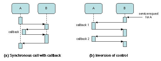
It may happen that the provision of a service by B to A relies on the use by B of a service provided by A (the contract between service provider and customer implies commitment by both parties). For instance, in Figure 2.2a, the execution of the call from A to B relies on a callback from B to a function provided by A. In the example, the callback is executed by a new thread, while the original thread keeps waiting for the completion of the initial call.
Exceptions are a mechanism that deals with conditions considered as being outside the normal execution of a service, such as failures, out of range parameter values, etc. When such a condition occurs, execution of the service is cleanly terminated (e.g. resources are released) and control is returned to the caller, with an information on the nature of the exception. Thus an exception may be considered as a "one-way callback". It is the responsibility of the requester of the service to provide a handler for all possible exceptions.
The notion of a callback can be extended one step further. The service provided by B to A may be requested from an outside source, with A still providing one or several callbacks to B. This interaction pattern (Figure 2.2b) is called inversion of control, because the flow of control is from B (the provider) to A (the requester). It typically occurs when B is "controlling" A, i.e. providing administrative services such as monitoring or persistent saving; in this situation, the request for service originates from the outside, e.g. is triggered by an external event such as a timing signal.
Chapters/Basic/Figs/callback.gif
Figure 2.2: Inversion of control
This use of callbacks is further discussed in Chapter 7 .
The above interactions do not explicitly imply a notion of time other than event ordering. Continuous media, such as multimedia data, need a form of real-time synchronization. Multimedia data are exchanged through data streams, which allow continuous transmission of a sequence of data subject to timing constraints. This form of communication is examined in Chapter 11 .

2.1.2  Interfaces

An elementary service provided by a software component is defined by an interface, which is a concrete description of the interaction between the requester and the provider of the service. A complex service may be defined by several interfaces, each of which represents a particular aspect of the service. There are actually two complementary views of an interface.
The actual definition of an interface therefore requires a concrete representation for both views, e.g. a programming language for the usage view and a specification language for the contract view.
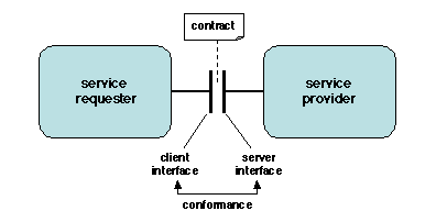
Recall that both the usage view and the contract view involve two parties3: the requester and the provider. As a consequence, the provision of a service actually involves two interfaces: the interface provided by the component that delivers a service, and the interface expected by the customer of the service. The provided (or server) interface should be "conformant" (i.e. compatible) with the required (or client) interface; we shall come back to the definition of conformance.
Chapters/Basic/Figs/interface.gif
Figure 2.3: Interfaces
The concrete representation of an interface, be it provided or expected, consists of a set of operations, which may take a variety of forms, corresponding to the interaction patterns described in 2.1.1.
The concrete representation of contracts is examined in 2.1.3.
A number of notations, known as Interface Description Languages (IDL), have been designed to formally describe interfaces. There is currently no single common model of an IDL, but the syntax of most existing IDLs is inspired by that of a procedural programming language. Some programming languages (e.g. Java, C#) actually include the notion of an interface and therefore define their own IDL. A typical interface definition specifies the signature of each operation, i.e. its name, the type and mode of transmission of its parameters and return values, and the exceptions it may raise during execution (the requester is expected to provide handlers for these exceptions).
The representation of an interface, together with the associated contract, completely defines the interaction between the requester and the provider of the service that the interface represents. Therefore neither the requester nor the provider should make any assumption on the other party, beyond the information explicitly specified in the interface. In other words, anything beyond the client or server interface is seen by the other party as a "black box". This rule is known as the encapsulation principle, which is a special instance of separation of concerns. The encapsulation principle ensures independence between interface and implementation, and allows a system to be modified by "plug and play", replacing a part by a different one provided the interfaces between the replaced part and the rest of the system remain compatible.

2.1.3  Contracts and Interface Conformance

The contract between the provider and the customer of a service may take a variety of forms, depending on the specified properties and on the more or less formal expression of the specification. For instance, the term Service Level Agreement (SLA) is used for a legal contract between the provider and the customer of a global, high level service (e.g. between an Internet Service Provider (ISP) and its clients).
From a technical point of view, different kinds of properties can be specified. Following [Beugnard et al. 1999], we may distinguish four levels of contracts.
Note again that the contract goes both ways, at all levels, i.e. it constrains the requester as well as the provider. For example, the parameters passed to a function call are constrained by their type; if the interface involves a callback, the callback procedure must be provided (this amounts to specifying a procedure-valued parameter).
The essence of an interface's contract is expressed by the notion of conformance. An interface I2 is said to conform to an interface I1 if a component that implements all methods specified in I2 may be used anywhere a component that implements all the methods specified in I1 may be used. In other words, I2 conforms to I1 if I2 satisfies I1's contract.
Conformance may be checked at each of the four above-specified levels. We examine them in turn.

Syntactic Contracts

A syntactic contract is based on the form of the operations. A common way of expressing such a contract is by using types. A type defines a predicate that applies to objects4 of that type. The type of an object X is noted T(X). The notion of conformance is expressed by subtyping: if T2 is a subtype of T1 (noted T2 \sqsubseteq T1), any object of type T2 is also an object of type T1 (in other words, an object of type T2 may be used anywhere an object of type T1 is expected). The subtyping relationship thus defined is called true (or conformant) subtyping.
Let us consider interfaces defined as a set of procedures. For such interfaces, conformant subtyping is defined as follows: an interface I2 is a subtype of an interface of type I1 (noted T(I2) \sqsubseteq T(I1)) if I2 has at least the same number of procedures as I1 (it may have more), and if for each procedure defined in I1 there is a conformant procedure in I2. A procedure Proc2 is said to be conformant with a procedure Proc1 when the following relationships hold between the signatures of these procedure.
These rules illustrate a general principle of substitutability: an entity E2 may be substituted for another entity E1 if E2 "provides more and requires less" than E1. Here "provides" and "requires" must be adapted to each specific situation (e.g. in a procedure call, the entry parameters are "required" and the result is "provided"). Also "more" and "less" respectively refer to the notions of subtype and supertype, and include equality.
Note that the subtyping relationship defined in most programming languages usually fails to satisfy parameter type contravariance and is therefore not a true subtyping relationship. In such case (e.g. in Java), some conformance errors may not be statically detected, and must be caught by a run time check.
The notion of conformance may be extended to other forms of interface definitions, e.g. those containing event sources or sinks, or data streams. Examples are found in Chapters 6 , 7 , and 12 .
Recall that the relationship between types is purely syntactic and does not catch the semantics of conformance. Verifying semantics is the goal of behavioral contracts.

Behavioral Contracts

Behavioral contracts are based on a method proposed in [Hoare 1969] to prove properties of programs, using pre- and post-conditions together with proof rules based on first-order logic. Let A be a sequential action. Then the notation
{P} A {Q},
in which P and Q are assertions (predicates on the state of the program's universe), says the following: if the execution of A is started in a state in which P holds, and if A terminates, then Q holds at the end of A. An additional condition may be specified in the form of an invariant predicate I that should be preserved by the execution of A. Thus if P and I hold initially, Q and I hold at the end of A, if A terminates. The invariant may be used to specify a consistency constraint.
This may be transposed as follows in terms of services and contracts. Before the execution of a service, it is the responsibility of the requester to ensure that the pre-condition P and the invariant I actually hold. It is the responsibility of the provider of the service to ensure that the service is actually delivered in finite time, and that the post-condition Q and the invariant I hold at the end. Possible cases of abnormal termination must be specified in the contract and handled by retrying or by exception raising. This method has been developed under the name of "design by contract" [Meyer 1992] through extensions to the Eiffel language allowing the expression of pre- and post-conditions and invariant predicates. These conditions are checked at run time. Similar tools have been developed for Java [Kramer 1998].
The notion of subtyping may be extended to behavioral contracts, by specifying the conformance constraints for assertions. Consider a procedure Proc1 defined in interface I1, and the corresponding (conformant) procedure Proc2 defined in interface I2, such that T(I2) \sqsubseteq T(I1). Let P1 and Q1 (resp. P2 and Q2) be the pre- and post-condition defined for Proc1 (resp. Proc2). The following conditions must hold:
P1 Þ P2 and Q2 Þ Q1
In other words, a subtype has weaker pre-conditions and stronger post-conditions than its supertype, which again illustrates the substitutability principle.

Synchronization Contracts

The expression of program correctness by means of assertions may be extended to concurrent programs. The goal here is to separate, as much as possible, the description of synchronization constraints from the code of the procedures. An early proposal is path expressions [Campbell and Habermann 1974], which specify constraints on the ordering and on the concurrency of procedure executions. Further developments (synchronization counters, synchronization policies) were essentially extensions and improvements of this construct, whose implementation relies on run time mechanisms generated from the static constraint description. Several articles describing proposals in this area may be found in [CACM 1993], but these techniques have not found a wide application.
A very simple form of synchronization contract is the synchronized clause of Java, which specifies execution in mutual exclusion. Another example includes the selection of a queue management policy (e.g. FIFO, priority, etc.) for a shared resource, among a predefined set.
Current efforts aim at allowing compile-time checking of the synchronization constraints, in order to detect incompatibilities at an early stage. An example of recent work in this area is [Chakrabarti et al. 2002].

Quality of Service Contracts

The specifications associated with the interface of a system or part of a system, be they or not expressed in a formal way, are called functional. A system may be subject to additional specifications, which apply to some of its aspects that do not explicitly appear in the interface. Such specifications are called extra-functional5. Quality of Service (another name for these properties) includes the following aspects.
Other extra-functional aspects that are difficult to quantify include maintainability and ease of evolution.
Since most aspects of quality of service depend on a changing environment, it is important that the policies of QoS management should be adjustable. Therefore QoS contracts usually include the possibility of negotiation, i.e. redefining the terms of the contract through run-time exchanges between the requester and the provider of the service.

2.2  Architectural Patterns

In this section, we review a few basic principles for structuring middleware systems. Most of the systems examined in this book are organized around these principles, which essentially provide guidelines for decomposing a complex system into parts.

2.2.1  Multilevel Architectures

Layered Architectures

Decomposing a complex system into layers of abstraction is an old and powerful organizational principle. It pervades many areas of system design, through such widely used notions as virtual machines and protocol stacks.
Abstraction is a conceptual process by which a designer builds a simplified view of a system as a set of interfaces. The implementation of these interfaces in terms of more detailed entities is left to a further refinement step. A complex system may thus be described at different levels of abstraction. In the simplest organization (Figure 2.4a), each level i defines its own entities, which provide an interface to the upper level (i+1). These entities are implemented using the interface provided by the lower level (i-1), down to a predefined base level (usually implemented in hardware). This architecture is described in [Buschmann et al. 1995] as the LAYERS pattern.
Chapters/Basic/Figs/layers.gif
Figure 2.4: Layered system organizations
The interface provided by each level may be viewed as set of functions defining a library, in which case it is often called an Application Programming Interface6 (API). An alternative view is to consider each level as a virtual machine, whose "language" (i.e. instruction set) is defined by its interface. By virtue of the encapsulation principle, a virtual machine hides the implementation details of all the lower levels. Virtual machines [Smith and Nair 2005] have been used to emulate a computer, an operating system, or a network on top of a different one, to emulate a number of computers in order to multiplex physical resources, or to implement the run time environment of a programming language (e.g. the Java Virtual Machine [Lindholm and Yellin 1996]).
This basic scheme may be extended in several ways. In the first extension (Figure 2.4b), a layer at level i may use (part of) the interfaces provided by the machines at the lower layers. In the second extension, a layer at level i may callback the layer at level i+1, using a callback interface provided by that layer. In this context, callbacks are known as upcalls (referring to the "vertical" layer hierarchy).
Although upcalls may be synchronous, their most frequent use is to propagate asynchronous events up the layer hierarchy. Consider the structure of an operating system kernel. The upper (application) layer activates the kernel through synchronous downcalls, using the system call API. The kernel also activates hardware-provided functions (e.g. updating a MMU, sending a command to a disk drive) through the equivalent of synchronous calls. On the other hand, the hardware typically activates the kernel through asynchronous interrupts (upcalls), which trigger the execution of handlers. This calling structure is often repeated in the upper layers, i.e. each layer receives synchronous calls from the upper layer, and asynchronous calls from the lower layer. This organization is described in [Schmidt et al. 2000] as the HALF SYNC, HALF ASYNC pattern. It is widely used in communication protocols, as described in Chapter 4 .

Multitier Architectures

The advent of distributed systems has promoted a different form of multilevel architecture. Consider the historical evolution of a common form of client-server applications, in which a client's requests are processed using information stored in a database.
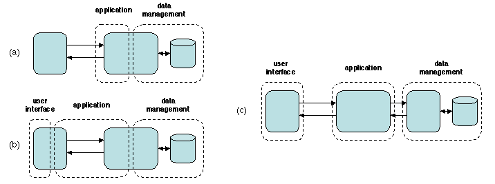
In the 1970s (Figure 2.5a), both the data management functions and the application itself are executed on a mainframe. The client's terminal is a simple display, which implements a primitive form of user interface.
In the 1980s (Figure 2.5b), workstations are available as client machines, and allow elaborate graphical user interface (GUI) facilities to be implemented. The processing capabilities of the workstation allow it to take up a part of the application processing, thus reducing the load of the server and improving scalability (since the addition of a new client station contributes processing power to the application).
The drawback of this architecture is that the application is now split between the client and the server machines; the communication interface is now internal to the application. Modifying the application may now involve changes both on the client and the server machines, and possibly a change in the communication interface.
Chapters/Basic/Figs/multitier.gif
Figure 2.5: Multitier architectures
These drawbacks are corrected by the architecture shown on Figure 2.5c, introduced in the late 1990s. The functions of the application are split between three machines: the client station only supports the functions of the GUI, the application proper resides on a dedicated server, and the management of the database is devoted to another machine. Each of these "horizontal" divisions is called a tier. Further specialization of the functions leads to other multitier architectures. Note that each tier may itself be subject to a "vertical" layered decomposition into abstraction levels.
The multitier architecture still has the benefits of scalability, as the application machine may be incrementally upgraded (e.g. by adding a machine to a cluster). In addition, the interfaces between the tiers may be designed to favor separation of concerns, since logical interfaces now coincide with communication interfaces. For example, the interface between the application tier and the data management tier can be made generic, in order to easily accommodate a new type of database, or to connect to a legacy application, using an adapter (2.3.3) for interface conversion.
Examples of multitier architectures are presented in Chapter 7 .

Frameworks

A software framework is a program skeleton that may be directly reused, or adapted according to well-defined rules, to solve a family of related problems. This definition covers many cases; here we are interested in a particular form of frameworks that consists of an infrastructure in which software components may be inserted in order to provide specific services. Such frameworks illustrate some notions related to interfaces, callbacks, and inversion of control.
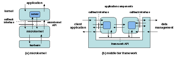
The first example (Figure 2.6a) is the microkernel, an architecture introduced in the 1980s in an attempt to develop flexible operating systems. A microkernel-based operating system consists of two layers.
In most microkernel-based organizations, an operating system kernel is structured as a set of servers, each of which is in charge of a specific function (e.g. process management, file system, etc.). A typical system call issued by an application is processed as follows.
Adding a new function to a kernel is done by developing and integrating a new server.
Chapters/Basic/Figs/frameworks.gif
Figure 2.6: Framework architectures
The second example (Figure 2.6b) illustrates a typical organization of the middle tier of a 3-tier client-server architecture. The middle tier framework interacts with both the client and the data management tiers, and mediates the interaction between these tiers and the server application program. This program is made up of application components, which use the API provided by the framework and must supply a set of callback interfaces. Thus a client request is handled by the framework, which activates an appropriate application component, interacts with it using its own API and the component's callback interface, and finally returns to the client.
Detailed examples of this organization are presented in Chapter 7 .
Both above examples illustrate inversion of control. To provide its services, the framework uses callbacks to externally supplied software modules (servers in the microkernel example, or application components in the middle tier example). These modules must respect the framework contract, by providing a specified callback interface, and by using the framework API.
The layered and multitier organizations define a large grain structure for a complex system. Each layer or tier (or layer in a tier) is itself organized using finer grain entities. Objects, a common way of defining this fine grain structure, are presented in the next section.

2.2.2  Distributed Objects

Objects in Programming

Objects have been introduced in the 1960s as a means of structuring computing systems. While there are many definitions for objects, the following properties capture the most common object-related concepts, especially in the context of distributed computing.
An object, in a programming model, is a software representation of a real-world entity (such as a person, a bank account, a document, a car, etc.). An object is the association of a state and of a set of procedures (or methods) that operate on that state. The object model that we consider has the following properties.
Recall that these definitions are not universal, and are not applicable to all object models (e.g. there are other mechanisms than classes to create instances, objects may be active, etc.), but they are representative of a vast set of models used in current practice, and are embodied in such languages as Smalltalk, C++, Eiffel, Java, or C#.

Remote Objects

The above properties make objects specially well suited as a structuring mechanism for distributed systems.
The simplest and most common way of distributing objects is to allow the objects that make up an application to to be located on distributed sites (other ways of distributing objects are described in Chapter 5 ). A client application may use an object located on a remote site by calling a method of the object's interface, as if the object were local. Objects used in this way are called remote objects, and a method call on a remote object is called Remote Method Invocation; it is a transposition of RPC to the world of objects.
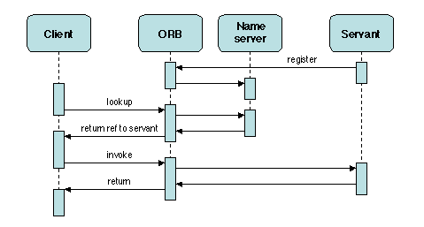
Remote objects are an example of a client-server system. Since a client may use several different objects located on a remote site, different words are used to designate the remote site (the server site) and an individual object that provides a specific service (a servant object). To make the system work, an appropriate middleware must locate an implementation of the servant object on a possibly remote site, send the parameters to the object's location, actually perform the call, and return the results to the caller. A middleware that performs these tasks is an Object Request Broker, or ORB.
Chapters/Basic/Figs/orb.gif
Figure 2.7: Remote Method Invocation
The overall structure of a call to a remote object (Figure 2.7) is similar to that of an RPC: the remote object must first be located, which is usually done by means of a name server or trader (Chapter 3 ); then the call itself is performed. Both the lookup and the invocation are mediated through the ORB. The internal organization of an ORB is examined in detail in Chapter 5 .

2.3  Patterns for Distributed Object Middleware

Remote execution mechanisms rely on a few design patterns, which have been widely described in the literature, specially in [Gamma et al. 1994], [Buschmann et al. 1995], and [Schmidt et al. 2000]. In this presentation, we concentrate on the specific use of these patterns for distributed object middleware, and we discuss their similarities and differences. For an in-depth discussion of these patterns, the reader is directed to the specified references.

2.3.1  Proxy

The PROXY pattern is one of the first design patterns identified in distributed programming [Shapiro 1986]. While its application domain has been extended to many other aspects [Buschmann et al. 1995], we only discuss here the use of PROXY for distributed objects.
  1. Context. This pattern is used for applications organized as a set of objects in a distributed environment, communicating through remote method invocation: a client requests a service provided by some possibly remote object (the servant).

  2. Problem. Define an access mechanism that does not involve hard-coding the location of the servant into the client code, and does not necessitate deep knowledge of the communication protocols by the client

  3. Desirable Properties. Access should be efficient at run time. Programming should be simple for the client; ideally there should be no difference between local and remote access (this property is known as access transparency).

  4. Constraints. The main constraint results from the distributed environment: the client and the server are in different address spaces.

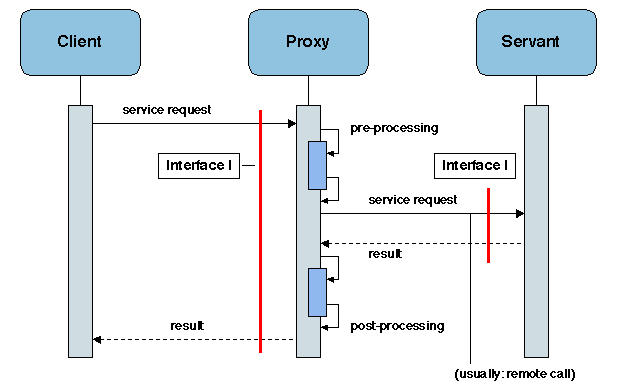
  5. Solution. Use a local representative of the server on the client site. This representative has exactly the same interface as the servant. All information related to the communication system and to the location of the servant is hidden in the proxy, and thus invisible to the client.
    The organization of the proxy is shown on Figure 2.8.
    Chapters/Basic/Figs/proxy.gif
    Figure 2.8: Proxy
    The internal structure of the proxy follows a well-defined pattern, which facilitates its automatic generation.

  6. Known Uses.
    In middleware construction, proxies are used as local representatives for remote objects. They do not add any functionality. Examples may be found in Chapter 5 .
    Some variants of proxies contain additional functions. Examples are client-side caching and client-side adaptation. In this latter case, the proxy may filter server output to adapt it to specific client display capabilities, such as low resolution. Such "smart" proxies actually combine the standard functions of a proxy with those of an interceptor (2.3.4).

  7. References.
    Discussions of the PROXY pattern may be found in [Gamma et al. 1994], [Buschmann et al. 1995].

2.3.2  Factory

  1. Context. Applications organized as a set of objects in a distributed environment (the notion of "object" in this context may be quite general, and is not limited to objects as defined in object-oriented languages).

  2. Problem. Dynamically create families of related objects (e.g. instances of a class), while allowing some decisions to be deferred to run time (e.g. choosing a concrete class to implement a given interface).

  3. Desirable Properties. The implementation details of the created objects should be abstracted away. The creation process should allow parameters. Evolution of the mechanism should be easy (no hard-coded decisions).

  4. Constraints. The main constraint results from the distributed environment: the client (requesting object creation) and the server (actually performing creation) are in different address spaces.

  5. Solution. Use two related patterns: an ABSTRACT FACTORY defines a generic interface and organization for creating objects; the actual creation is deferred to concrete factories. ABSTRACT FACTORY may be implemented using FACTORY METHODS (a creation method that is redefined in a subclass).
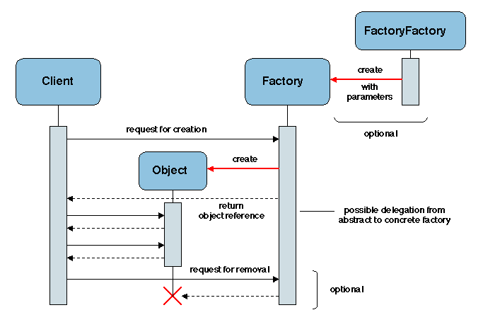
    Another way of achieving flexibility is to use a Factory Factory, as shown on Figure 2.9 (the creation mechanism itself is parameterized).
    A Factory may also be used as a manager of the objects that it has created, and may thus implement a method to look up an object (returning a reference for it), and to remove an object upon request.
    Chapters/Basic/Figs/factory.gif
    Figure 2.9: Factory


  6. Known Uses.
    FACTORY is one of the most widely used patterns in middleware. It is both used in applications (to create remote instances of application objects) and within middleware itself (one example is binding factories, described in Chapter 3 ). Factories are also used in relation to components (Chapter 7 ).

  7. References.
    The two patterns ABSTRACT FACTORY and FACTORY METHOD are described in [Gamma et al. 1994].

2.3.3  Adapter

  1. Context. Service provision, in a distributed environment: a service is defined by an interface; clients request services; servants, located on remote servers, provide services.

  2. Problem. Reuse an existing servant by providing a different interface for its functions in order to comply to the interface expected by a client (or class of clients).

  3. Desirable Properties. The interface conversion mechanism should be run-time efficient. It should also be easily adaptable, in order to respond to unanticipated changes in the requirements (e.g. the need to reuse a new class of applications). It should be reusable (i.e. generic).

  4. Constraints. No specific constraints.

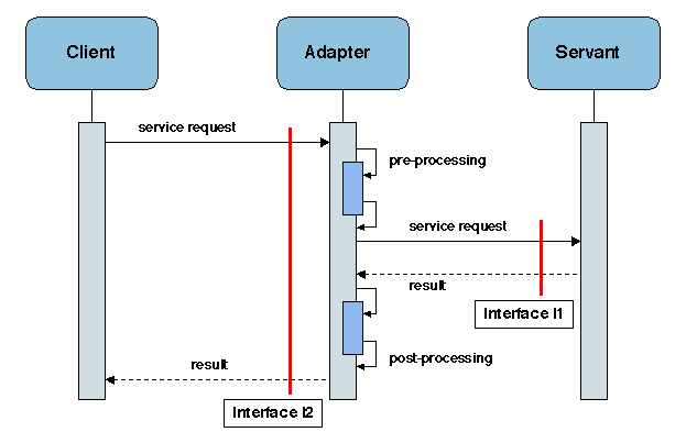
  5. Solution. Provide a component (the adapter, or wrapper) that screens the servant by intercepting method calls to its interface. Each call is prefixed by a prologue and followed by an epilogue in the adapter (Figure 2.10). The parameters and results may need to be converted.
    Chapters/Basic/Figs/wrapper.gif
    Figure 2.10: Adapter
    In some simple cases, an adapter can be automatically generated from the description of the provided and required interfaces.

  6. Known Uses.
    Adapters are widely used in middleware to encapsulate server-side functions. Examples include the Portable Object Adapter (POA) of CORBA (Chapter 5 ), and the various adapters for reusing legacy systems, such as the Java Connector Architecture (JCA).

  7. References.
    ADAPTER (also known as WRAPPER) is described in [Gamma et al. 1994]. A related pattern is WRAPPER FAçADE ([Schmidt et al. 2000]), which provides a high-level (e.g. object-oriented) interface to low level functions.

2.3.4  Interceptor

  1. Context. Service provision, in a distributed environment: a service is defined by an interface; clients request services; servants, located on remote servers, provide services. There is no restriction on the form of communication (e.g. uni- or bi-directional, synchronous or asynchronous).

  2. Problem. One wants to enhance an existing service with new capabilities, or to provide it by different means.

  3. Desirable Properties. The mechanism should be generic (applicable to a wide variety of situations). It should allow static (compile time) or dynamic (run time) service enhancement.

  4. Constraints. Services may be added or removed dynamically.

  5. Solution. Create interposition objects (statically or dynamically). These objects intercept calls (and/or returns) and insert specific processing, that may be based on contents analysis. An interceptor may also redirect a call to a different target.
    Chapters/Basic/Figs/simple-interceptor.gif
    Figure 2.11: Simple forms of Interceptor
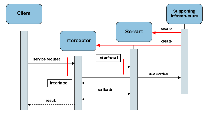
    This mechanism may be implemented in a variety of forms. In the simplest form, an interceptor is a module that is inserted at a specified point in the call path between the requester and the provider of a service (Figure 2.11a and 2.11b). It may also be used as a switch between several servants that may provide the same service with different enhancements (Figure 2.11c), e.g. provision for fault tolerance, load balancing or caching.
    In a more general form (Figure 2.12, interceptors and service providers (servants) are managed by a common infrastructure and created upon request. The interceptor uses the servant interface and may also rely on services provided by the infrastructure. The servant may provide callback functions to be used by the interceptor.

  6. Known Uses.
    Interceptors are used in a variety of situations in middleware systems.
    Chapters/Basic/Figs/interceptor.gif
    Figure 2.12: General Interceptor


  7. References.
    The INTERCEPTOR pattern is described in [Schmidt et al. 2000].

2.3.5  Comparing and Combining Patterns

Three of the patterns described in the previous section ( PROXY, ADAPTER, and INTERCEPTOR) have close relationships to each other. They all involve a software module being inserted between the requester and the provider of a service. We briefly discuss their similarities and differences.
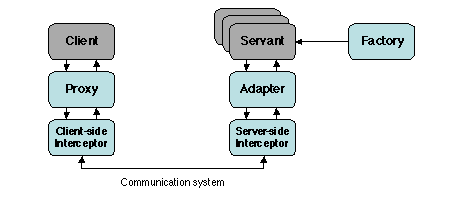
Using the above patterns, we may draw a first approximate and incomplete picture of the overall organization of an ORB (Figure 2.13).
Chapters/Basic/Figs/combine.gif
Figure 2.13: Using patterns in an ORB
The main missing aspects are those related to binding and communication, which are described in Chapters 3  and 4 , respectively.

2.4  Achieving Adaptability and Separation of Concerns

Three main approaches are being used to achieve adaptability and separation of concerns in middleware systems: meta-object protocols, aspect-oriented programming, and pragmatic approaches. They are summarized in the following subsections.

2.4.1  Meta-Object Protocols

Reflection has been introduced in 1.4.2 . Recall that a reflective system is one that is able to answer questions about itself and to modify its own behavior, by providing a causally connected representation of itself.
Reflection is a desirable property for middleware, because a middleware system operates in a changing environment and needs to adapt its behavior to changing requirements. Reflective capabilities are present in most existing middleware systems, but they are usually introduced locally, for isolated features. Middleware platforms that integrate reflection in their basic architecture are being developed as research prototypes [RM 2000].
A general approach to designing a reflective system is to organize it into two levels.
This decomposition may be iterated, by considering the meta-level as a base level for a meta-meta-level, and so on, thus defining a so-called "reflective tower". In most practical cases, the height of the tower is limited to two or three levels.
Defining a representation of the base level, to be used by the meta-level, is a process called reification. It results in the definition of meta-objects, each of which is a representation, at the meta-level, of a data structure or operation defined at the base level. The operation of the meta-objects, and their relationship to the base level entities, are specified by a meta-object protocol (MOP) [Kiczales et al. 1991].
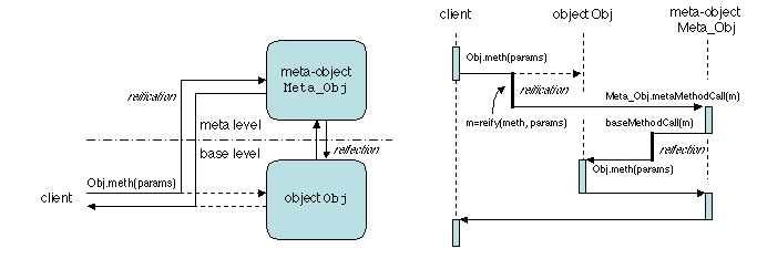
A simple example of a MOP (borrowed from [Bruneton 2001]) is the reification of a method call in a reflective object-oriented system. At the meta-level, a meta-object Meta_Obj is associated with each object Obj. A method call Obj.meth(params) is executed in the following steps (Figure 2.14).
  1. The method call is reified into an object m, which contains a representation of meth and params. The precise form of this representation is defined by the MOP. This object m is transmitted to the meta-object, which executes Meta_Obj.meta_MethodCall(m).
    Chapters/Basic/Figs/meta-call.gif
    Figure 2.14: Performing a method call in a reflective system


  2. The method meta_MethodCall(m) then executes any processing specified by the MOP. To take simple examples, it may print the name of the method (by calling a method such as m.methName.printName()) before actually executing it (for tracing) or it may save the state of the object prior to the method call (to allow undo operations), or it may check the value of the parameters, etc.

  3. The meta-object may now actually execute the initial call7, by invoking a method baseMethodCall(m) which essentially performs Obj.meth(params)8. This step (the inverse of reification) is called reflection.

  4. The meta-object then executes any post-processing defined by the MOP, and returns to the initial caller.

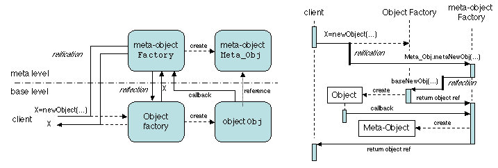
Likewise, the operation of object creation may be reified by calling a meta-object factory (at the meta-level). This factory creates a base-level object, using the base-level factory; the new object then upcalls the meta-object factory, which creates the associated meta-object, and executes any additional operations specified by the MOP (Figure 2.15).
Chapters/Basic/Figs/meta-new.gif
Figure 2.15: Object creation in a reflective system
Examples of using meta-object protocols in middleware may be found in Chapters 5  and 10 .

2.4.2  Aspect-Oriented Programming

Aspect-oriented programming (AOP) [Kiczales 1996] is motivated by the following remarks.
The goal of AOP is to define methods and tools to better identify and isolate the code related to the various aspects present in an application. More precisely, an application developed using AOP is built in two phases.
A join point is a place, in the source code of the base program, where aspect-related code can be inserted. Aspect weaving relies on two main notions: point cut, i.e. the specification of a set of join points according to a given criterion, and advice, i.e. the definition of the interaction of the inserted code with the base code. For example, if AOP is added to an object-oriented language, a particular point cut may be defined as the set of invocation points of a family of methods (specified by a regular expression), or the set of invocations of a specified constructor, etc. An advice specifies whether the inserted code should be executed before, after, or in replacement for the operations located at the point cuts (in the latter case, these operations may still be called from within the inserted code). Composition may be done statically (at compile time), dynamically (at run time), or using a combination of static and dynamic techniques.
One important problem with AOP is the composition of aspects. For instance, if different pieces of aspect-related code are inserted at the same join point, the order of insertion may be relevant if the corresponding aspects are not independent. Such issues cannot usually be settled by the weaver and call for additional specification.
Two examples of tools that implement AOP are AspectJ [Kiczales et al. 2001] and JAC [Pawlak et al. 2001]. Both apply to base programs written in Java.

AspectJ

AspectJ allows aspects to be defined by specifying pointcuts and advices, in a Java-like notation. A weaver integrates the aspects and the base program into Java source code, which may then be compiled.
A simple example gives an idea of the capabilities of AspectJ. The following code describes an aspect, in the form of pointcut definition and advice.

public aspect MethodWrapping{

/* point cut definition */
    pointcut Wrappable(): call(public * MyClass.*(..));

/* advice definition    */
    around(): Wrappable() {
        /* prelude: a sequence of code to be inserted before the call */
           proceed (); /* performs the call to the original method    */
        /* postlude: a sequence of code to be inserted after the call */
    }
}

The first part of the description defines a point cut as the set of invocations of any public method of class MyClass. The advice part says that a call to such a method should be replaced by a specified prelude, followed by a call to the original method, followed by a specified postlude. In effect, this amounts to placing a simple wrapper (without interface modification) around each method call specified in the pointcut definition. This may be used to add logging facilities to an existing application, or to insert testing code to evaluate pre- and post-conditions for implementing design by contract (2.1.3).
Another capability of AspectJ is introduction, which allows additional declarations and methods to be inserted at specified places in an existing class or interface. This facility should be used with care, since it may break the encapsulation principle.

JAC

JAC (Java Aspect Components) has similar goals to AspectJ. It allows additional capabilities (method wrapping, introduction) to be added to an existing application. JAC differs from AspectJ on the following points.
Thus JAC provides added flexibility, but at the expense of a higher runtime overhead due to the dynamic weaving of the aspects into the bytecode.

2.4.3  Pragmatic Approaches

Pragmatic approaches to reflection in middleware borrow features from the above systematic approaches, but tend to apply them in an ad hoc fashion, essentially for efficiency reasons. These approaches are essentially based on interception.
Many middleware systems involve an invocation path from a client to a remote server, traversing several layers (application, middleware, operating system, communication protocols). Interceptors may be inserted at various points of this path, e.g. at the send and receive operations of requests and replies.
Inserting interceptors allows non-intrusive extension of middleware functionality, without modifying the application code or the middleware itself. This technique may be considered as an ad hoc way of implementing AOP: the insertion points are the join points and the interceptors directly implement aspects. By adequately specifying the insertion points for a given class of middleware, conforming to a specific standard (e.g. CORBA, EJB), the interceptors can be made generic and may be reused with different implementations of the standard. The functions that may be added or modified through interceptors include monitoring, logging and measurement, security, caching, load balancing, replication. A detailed example of using interceptors in CORBA may be found in Chapter 5 .
This technique may also be combined with a meta-object protocol, i.e. the interceptors may be inserted in the reified section of the invocation path (i.e. within a meta-level).
Interception techniques entail a run time overhead. This may be alleviated by using code injection, i.e. directly integrating the code of the interceptor into the code of the client or the server (this is the analog of inlining the code of procedures in an optimizing compiler). To be efficient, this injection must be done at a low level, i.e. in assembly code, or (for Java) at the bytecode level, using bytecode manipulation tools such as BCEL [BCEL ], Javassist [Tatsubori et al. 2001], or ASM [ASM ]. To maintain flexibility, it should be possible to revert the code injection process by going back to the separate interception form. An example of use of code injection may be found in [Hagimont and De Palma 2002].

2.4.4  Comparing Approaches

The main approaches to separation of concerns in middleware may be compared as follows.
  1. Approaches based on meta-object protocols are the more general and systematic. However, they entail a potential overhead due to the back and forth interaction between meta- and base-levels.

  2. Approaches based on aspects operate on a finer grain that those based on MOPs and provide more flexibility, at the expense of generality. The two approaches may be combined, e.g. aspects can be used to modify operations both at the base and meta levels.

  3. Approaches based on interception provide restricted capabilities with respect to MOP or AOP, but provide acceptable solutions for a number of frequent situations. They are still lacking a formal model on which design and verification tools could be based.

In all cases, optimization techniques based on low-level code manipulation may be applied. This area is the subject of active research.

2.5  Historical Note

Architectural concerns in software design appeared in the late 1960s. The THE operating system [Dijkstra 1968] was an early example of a complex system designed as a hierarchy of abstract machines. The notion of object-oriented programming was introduced in the Simula-67 language [Dahl et al. 1970]. Modular construction, an approach to systematic program composition as an assembly of parts, appeared in the same period. Design principles developed for architecture and city planning [Alexander 1964] were transposed to program design and had a significant influence on the emergence of software engineering as a discipline [Naur and Randell 1969].
The notion of a design pattern came from the same source a decade later [Alexander et al. 1977]. Even before that notion was systematically used, the elementary patterns described in the present chapter had been identified. Simple forms of wrappers were developed for converting data from one format to another one, e.g. in the context of database systems, before being used to transform access methods. An early use of interceptors is found in the implementation of the first distributed file system, Unix United [Brownbridge et al. 1982]: a software layer interposed at the Unix system call interface allows operations on remote files to be transparently redirected. This method was later extended [Jones 1993] to include user code in system calls. Stacked interceptors, both on the client and server side, were introduced in [Hamilton et al. 1993] under the name of subcontracts. Various forms of proxies have been used to implement remote execution, before the pattern was identified [Shapiro 1986]. Factories seem to have first appeared in the design of graphical user interfaces (e.g. [Weinand et al. 1988]), in which a number of parameterized objects (buttons, window frames, menus, etc.) are dynamically created.
A systematic exploration of software design patterns was initiated in the late 1980s. After the publication of [Gamma et al. 1994], activity expanded in this area, with the launching of the PLoP conference series [PLoP ] and the publication of several specialized books [Buschmann et al. 1995,Schmidt et al. 2000,Völter et al. 2002].
The idea of reflective programming was present in various forms since the early days of computing (e.g. in the evaluation mechanism of functional languages such as Lisp). First attempts towards a systematic use of this notion date from the early 1980s (e.g. the metaclass mechanism in Smalltalk-80); the foundations of reflective computing were laid out in [Smith 1982]. The notion of a meta-object protocol [Kiczales et al. 1991] was introduced for the CLOS language, an object extension of Lisp. Reflective middleware [Kon et al. 2002] has been the subject of active research since the mid-1990s, and some of its notions begin to slowly penetrate commercial systems (e.g. through the CORBA standard for portable interceptors).

References

[Alexander 1964]
Alexander, C. (1964). Notes on the Synthesis of Form. Harvard University Press.
[Alexander et al. 1977]
Alexander, C., Ishikawa, S., and Silverstein, M. (1977). A Pattern Language: Towns, Buildings, Construction. Oxford University Press. 1216 pp.
[ASM ]
ASM. A Java bytecode manipulation framework. http://www.objectweb.org/asm.
[BCEL ]
BCEL. Byte Code Engineering Library. http://jakarta.apache.org/bcel.
[Beugnard et al. 1999]
Beugnard, A., Jézéquel, J.-M., Plouzeau, N., and Watkins, D. (1999). Making Components Contract Aware. IEEE Computer, 32(7):38-45.
[Bieber and Carpenter 2002]
Bieber, G. and Carpenter, J. (2002). Introduction to Service-Oriented Programming. http://www.openwings.org.
[Brownbridge et al. 1982]
Brownbridge, D. R., Marshall, L. F., and Randell, B. (1982). The Newcastle Connection - or UNIXes of the World Unite! Software-Practice and Experience, 12(12):1147-1162.
[Bruneton 2001]
Bruneton, É. (2001). Un support d'exécution pour l'adaptation des aspects non-fonctionnels des applications réparties. PhD thesis, Institut National Polytechnique de Grenoble.
[Buschmann et al. 1995]
Buschmann, F., Meunier, R., Rohnert, H., Sommerlad, P., and Stal, M. (1995). Pattern-Oriented Software Architecture, Volume 1: A System of Patterns. John Wiley & Sons. 467 pp.
[CACM 1993]
CACM (1993). Communications of the ACM, special issue on concurrent object-oriented programming. 36(9).
[Campbell and Habermann 1974]
Campbell, R. H. and Habermann, A. N. (1974). The specification of process synchronization by path expressions. In Gelenbe, E. and Kaiser, C., editors, Operating Systems, an International Symposium, volume 16 of Lecture Notes in Computer Science, pages 89-102. Springer Verlag.
[Chakrabarti et al. 2002]
Chakrabarti, A., de Alfaro, L., Henzinger, T. A., Jurdzinski, M., and Mang, F. Y. (2002). Interface Compatibility Checking for Software Modules. In Proceedings of the 14th International Conference on Computer-Aided Verification (CAV), volume 2404 of Lecture Notes in Computer Science, pages 428-441. Springer-Verlag.
[Dahl et al. 1970]
Dahl, O.-J., Myhrhaug, B., and Nygaard, K. (1970). The SIMULA 67 common base language. Technical Report S-22, Norwegian Computing Center, Oslo, Norway.
[Dijkstra 1968]
Dijkstra, E. W. (1968). The Structure of the THE Multiprogramming System. Communications of the ACM, 11(5):341-346.
[Gamma et al. 1994]
Gamma, E., Helm, R., Johnson, R., and Vlissides, J. (1994). Design Patterns: Elements of Reusable Object Oriented Software. Addison-Wesley. 416 pp.
[Hagimont and De Palma 2002]
Hagimont, D. and De Palma, N. (2002). Removing Indirection Objects for Non-functional Properties. In Proceedings of the 2002 International Conference on Parallel and Distributed Processing Techniques and Applications.
[Hamilton et al. 1993]
Hamilton, G., Powell, M. L., and Mitchell, J. G. (1993). Subcontract: A flexible base for distributed programming. In Proceedings of the 14th ACM Symposium on Operating Systems Principles, volume 27 of Operating Systems Review, pages 69-79, Asheville, NC (USA).
[Hoare 1969]
Hoare, C. A. R. (1969). An axiomatic basis for computer programming. Communications of the ACM, 12(10):576-585.
[Jones 1993]
Jones, M. B. (1993). Interposition agents: Transparently interposing user code at the system interface. In Proceedings of the 14th ACM Symposium on Operating Systems Principles, pages 80-93, Asheville, NC (USA).
[Kiczales 1996]
Kiczales, G. (1996). Aspect-Oriented Programming. ACM Computing Surveys, 28(4):154.
[Kiczales et al. 1991]
Kiczales, G., des Rivières, J., and Bobrow, D. G. (1991). The Art of the Metaobject Protocol. MIT Press. 345 pp.
[Kiczales et al. 2001]
Kiczales, G., Hilsdale, E., Hugunin, J., Kersten, M., Palm, J., and Griswold, W. G. (2001). An overview of AspectJ. In Proceedings of ECOOP 2001, volume 2072 of Lecture Notes in Computer Science, pages 327-355, Budapest, Hungary. Springer-Verlag.
[Kon et al. 2002]
Kon, F., Costa, F., Blair, G., and Campbell, R. (2002). The case for reflective middleware. Communications of the ACM, 45(6):33-38.
[Kramer 1998]
Kramer, R. (1998). iContract - The Java Design by Contract Tool. In Proceedings of the Technology of Object-Oriented Languages and Systems (TOOLS) Conference, pages 295-307.
[Lindholm and Yellin 1996]
Lindholm, T. and Yellin, F. (1996). The Java Virtual Machine Specification. Addison-Wesley. 475 pp.
[Meyer 1992]
Meyer, B. (1992). Applying Design by Contract. IEEE Computer, 25(10):40-52.
[Naur and Randell 1969]
Naur, P. and Randell, B., editors (1969). Software Engineering: A Report On a Conference Sponsored by the NATO Science Committee, 7-11 Oct. 1968. Scientific Affairs Division, NATO. 231 pp.
[Pawlak et al. 2001]
Pawlak, R., Duchien, L., Florin, G., and Seinturier, L. (2001). JAC : a flexible solution for aspect oriented programming in Java. In Yonezawa, A. and Matsuoka, S., editors, Proceedings of Reflection 2001, the Third International Conference on Metalevel Architectures and Separation of Crosscutting Concerns, volume 2192 of Lecture Notes in Computer Science, pages 1-24, Kyoto, Japan. Springer-Verlag.
[PLoP ]
PLoP. The Pattern Languages of Programs (PLoP) Conference Series. http://www.hillside.net/conferences/plop.htm.
[RM 2000]
RM (2000). Workshop on Reflective Middleware. Held in conjunction with Middleware 2000, 7-8 April 2000. http://www.comp.lancs.ac.uk/computing/RM2000/.
[Schmidt et al. 2000]
Schmidt, D. C., Stal, M., Rohnert, H., and Buschmann, F. (2000). Pattern-Oriented Software Architecture, Volume 2: Patterns for Concurrent and Networked Objects. John Wiley & Sons. 666 pp.
[Shapiro 1986]
Shapiro, M. (1986). Structure and encapsulation in distributed systems: The proxy principle. In Proc. of the 6th International Conference on Distributed Computing Systems, pages 198-204, Cambridge, Mass. (USA). IEEE.
[Smith 1982]
Smith, B. C. (1982). Reflection And Semantics In A Procedural Language. PhD thesis, Massachusetts Institute of Technology. MIT/LCS/TR-272.
[Smith and Nair 2005]
Smith, J. E. and Nair, R. (2005). Virtual Machines: Versatile Platforms for Systems and Processes. Morgan Kaufmann. 638 pp.
[Tatsubori et al. 2001]
Tatsubori, M., Sasaki, T., Chiba, S., and Itano, K. (2001). A Bytecode Translator for Distributed Execution of "Legacy" Java Software. In ECOOP 2001 - Object-Oriented Programming, volume 2072 of Lecture Notes in Computer Science, pages 236-255. Springer Verlag.
[Völter et al. 2002]
Völter, M., Schmid, A., and Wolff, E. (2002). Server Component Patterns. John Wiley & Sons. 462 pp.
[Weinand et al. 1988]
Weinand, A., Gamma, E., and Marty, R. (1988). ET++ - An Object-Oriented Application Framework in C++. In Proceedings of OOPSLA 1988, pages 46-57.

Footnotes:

1In this chapter, we use the word component in a non-technical sense, to mean a unit of system decomposition. This notion is further elaborated in Chapter 7 .
2e.g. a computer delivers a specified service, on the provision of a specified power supply, and within a specified range of environmental conditions, such as temperature, humidity, etc.
3Some forms of service involve more than two parties, e.g. one provider with multiple requesters, etc. It is always possible to describe such situations by one to one relationships, e.g. by defining virtual interfaces that multiplex actual interfaces, etc.
4Here the term object designates any entity of interest in the present context, e.g. a variable, a procedure, an interface, a component.
5Note that the definition of a specification as "functional" or "extra-functional" is not absolute, but depends on the current state of the art: an aspect that is extra-functional today may become functional when technical advances allow its expression to be integrated into an interface.
6a complex interface may also be partitioned into several APIs, each one related to a specific function.
7it does not have to execute the initial call; for example, if the MOP is used for protection, it may well decide that the call should not be executed, and return to the caller with a protection violation message.
8note that it is not possible to directly invoke Obj.meth(params) because only the reified form of the method call is available to the meta-object and also because a post-processing step may be needed.


File translated from TEX by TTH, version 3.40.
On 27 Feb 2009, 12:58.