Middleware Architecture with Patterns and Frameworks

Chapter 4
Communication

[© 2003-2009 S. Krakowiak, Creative Commons license][pdf version][ps version]
Middleware relies on an underlying communication service, usually at the transport level. Providing communication services is also the main function of some middleware systems, which supply a higher level communication interface to applications. This chapter presents an architectural view of communication systems: how a communication system is constructed by combining more primitive ones, using uniform patterns. The main communication paradigms are first introduced, followed by a brief discussion of the main characteristics of communication systems. Then comes an introduction to the internal organization of a communication system, and a discussion of some underlying construction patterns. The chapter concludes with a description of the communication framework of Jonathan, an experimental open source communication toolkit, illustrated by simple use cases.

4.1  Introducing Communication Systems

In its simplest form, communication is the process of transmitting information between two entities: a sender and a receiver. A more general form of communication (broadcast and multicast), to be examined later, involves a sender and several receivers. In middleware systems, senders and receivers are usually activities (processes or threads) executing in a specified context (a machine, an application, an operating system, etc.).
The transmitted information is called a message; it may be as simple as a single bit (the occurrence of an elementary state transition), or as complex as an elaborate flow of data subject to timing constraints, such as a video stream.
Communication relies on a physical process whose interface is expressed in terms of actions on some physical medium. At the application level, communication is more conveniently viewed as a service, whose interfaces include high-level communication primitives. These interfaces may be specified in terms of messages, represented as data structures defined in application-specific terms. They also may have a more abstract form, an example of which is RPC (1.3 ), which encapsulates elementary message interchange within a high-level communication interface.
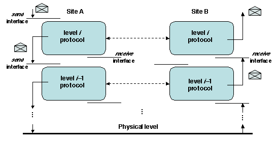
A communication system is the combination of hardware and software that provides a communication service to applications. In order to bridge the gap between the physical and application levels, a communication system is usually organized as a set of layers (2.2.1 ), in the form of a protocol stack. Each protocol specifies and implements the rules that govern communication at a given level; it defines its own communication abstractions and relies on the communication API provided by the lower level protocol in order to implement its own service, down to the physical level. Thus, at each level, communication may be seen as taking place over an abstract channel, which relies on (and hides) all the protocol layers below that level. Protocols and protocol stacks are discussed in detail in section 4.3.
At this stage, we only need to point out one aspect of this organization. A particular level may be chosen as the "base level" upon which more abstract upper layers are developed.
Chapters/XComm/Figs/base-high.gif
Figure 4.1: A view of a layered communication architecture
We can then introduce the notion of delivery of a message (at the upper layer interface) as distinct from its receipt (at the base layer interface). For example, the upper layer may reorder messages, so that the order of delivery may differ from the order of receipt; or it may drop duplicate messages. A similar distinction may be made at the sender end.
The base level and its interface are chosen to reflect the current interest: if the interest is in middleware, then the base level is usually the transport interface; if the interest is in the complete implementation of the transport protocol, then the base level may be chosen as the physical interface.


In the rest of this section, we examine the main characteristics that define a communication service, introducing them progressively. We concentrate on specification, leaving the architectural aspects for the next sections. The notions presented apply at any level of the protocol stack: communication takes place over the abstract channel implemented at that level.
We start with the simple case of an isolated message, assuming reliable transmission (4.1.1). We then assume the occurrence of failures, and we consider the constraints implied by multiple messages and multiple receivers (4.1.2). Other requirements (quality of service and security) are examined in section 4.2.

4.1.1  Single Message, Reliable Channel

We consider the sending of a single message between one sender and one or more receivers, and we assume that the communication is reliable, i.e., the message is delivered uncorrupted to all of the receivers.
In order to characterize the properties of communication, we need a classification framework. Various classification criteria have been proposed (e.g., [Tai and Rouvellou 2000], [Tanenbaum and van Steen 2006,Chap. 2], and [Eugster et al. 2003]). The framework that we propose borrows elements from these sources. It takes three aspects of communication into account.
  1. Designation of receivers. The designation may be explicit, i.e., the receivers of a message are directly designated by their names, or implicit, i.e., the set of receivers is determined by some other criterion (which may depend on the contents of the message). More details on multiple receivers are given in 4.1.2 and in Chapter 6 .

  2. Message persistence. The message may be transient, i.e., it is lost if no receiver is ready to receive it, or persistent, i.e., the communication system keeps the message until it is delivered to it receiver(s).

  3. Synchronization. The communication may be blocking, i.e., the sender thread or process is blocked until a response comes from the receiver (the nature of the response is elaborated further below), or non-blocking, i.e., the sender continues execution after the message has been sent1.

For each aspect, these options define different degrees of coupling between the sender and the receiver, as summarized in Table 4.1.
Coupling strong weak
Designation explicit implicit
Persistence persistent transient
Synchronization blocking non-blocking
Table 4.1: Degree of coupling in communication
There may be additional variations within these main classes. For instance, blocking message sending may have three possible meanings, for a single receiver, in order of increasing coupling: the sender is blocked until it receives notice that either a) the message has been received on the receiver's site; b) the message has been delivered to the receiver; c) the message has been processed by the receiver (assuming an answer is actually expected). In the case of multiple receivers, there are many more combinations, from the weakest (the message has been received on one receiver's site) to the strongest (the message has been processed by all receivers).
The strongest degree of coupling, for a single receiver, is represented by the combination (explicit, persistent, blocking-c), in which a message is sent to a specified receiver, the message persists until delivered, and the sender is blocked until the message has been answered. The weakest coupling is (implicit, transient, non-blocking), in which a message is sent to an unspecified set of receivers (the sender does not need to know the selection criteria for receivers), the message is transient (it is lost if no receiver is ready) and the sender continues execution after having sent the message.
Strong coupling tends to build a communication pattern close to that of centralized computing. Examples of strongly coupled communication services are RPC (1.3 ) and the various object invocation primitives described in Chapter 5 . Weak coupling, by contrast, tends to favor independence and late binding between sender an receivers. Examples of weakly coupled services are events, messages, and other coordination mechanisms described in Chapter 6 .

4.1.2  Multiple Receivers and Messages, Unreliable Channel

We now consider a more general situation, in which multiple senders and receivers communicate over a channel subject to failures. We identify three subproblems.
  1. How to build a reliable channel on top of an unreliable one.

  2. How to characterize the timing properties of communication.

  3. How to specify the properties of communication involving multiple senders and receivers.

We discuss these points in turn.

Building a Reliable Channel

Messages may be corrupted or lost, due to three main causes: (i) transmission errors at the physical level, due to noise or signal weakening; (ii) failures or overload conditions in communication software (e.g., packet loss in overloaded routers); and (iii) accidental cuts or disconnection, which break the physical connection between sender and receiver.
Fault tolerance mechanisms implemented at the lower levels of the protocol stack ensure that a message is delivered to its receiver as long as there exists a working physical communication link between the sender and the receiver. These mechanisms are based on redundancy, both in space (including additional bits in the message for error detection or correction) and in time (resending a message if loss or corruption has been detected).
The global effect of these mechanisms is to provide a reliable channel. Consider two processes, A and B, connected by such a channel; assume that A and B do not fail, and that the physical connection between them is preserved (i.e., restored after a cut or a disconnection). Then the following properties hold.
This essentially says that a message is eventually delivered unaltered to its receiver and that the channel does not generate spurious messages or duplicate actual messages. However, there may be no guarantee on the time needed to deliver the message. This is the subject of the next subsection.

Timing and Ordering Properties of Communication

A communication system is synchronous if there is a known upper bound on the transmission time of an elementary message2. If no such bound is known, the system is asynchronous. This property is essential in a distributed system, because it allows the use of timeouts to detect the failure of a remote node, assuming the channel is reliable. In an asynchronous system, it is impossible to distinguish a slow processor from a faulty one, which leads to a number of impossibility results for distributed algorithms in the presence of failures.
Unfortunately, most usual communication systems (e.g., the Internet) are asynchronous, because they rely on shared resources (e.g., routers) on which the load is unpredictable. In practice, many implementations of distributed algorithms use timeouts based on an estimated upper bound for message transmission time, and then must deal with late messages, which may arrive after the timeout.
Some applications have hard real-time constraints (i.e., a late message causes the application to fail), and therefore require a guaranteed upper bound on transmission time. This is usually achieved by resource reservation (see 4.2.1).
Some applications need to be aware of physical time. If the application is distributed, the physical clocks of the different nodes must then be synchronized, i.e., the drift (time difference) between the clocks at any two sites must be bounded. If the absolute time is relevant, then the drift between any local clock and an external time reference (a time server) must also be bounded. This is achieved by clock synchronization algorithms (see e.g., [Coulouris et al. 2005], section 11.3).
Even if an application has no constraints related to physical time, the relative order of events is important, since process synchronization is expressed by constraints on the order of events. Events on a site may be ordered by dating them with a local clock. Event ordering on different sites relies on communication, and is based on the causality principle: for any message m sent from process A to process B, the event "sending m" on A precedes the event "receiving m" on B. Based on this remark, one defines a system of logical clocks (first introduced in [Lamport 1978]), which preserves this ordering property, as well as local order on each site. These clocks capture a causal precedence relationship, noted ® (or happens before). For any two events e and e¢, e ® e¢ means that e is a potential cause of e¢, while e¢ cannot be not a cause of e. More elaborate ordering systems have been designed to capture causality more closely (see e.g., [Babaoglu and Marzullo 1993]). Thus communication is a basic mechanism for event ordering in a distributed system.

Broadcast and Multicast

We now turn to the definition of communication involving multiple receivers. We start by defining a process group as a set of related processes associated with a set of protocols for managing group membership (e.g., joining or leaving the group, determining the current composition of the group) and communication. The main motivations for process groups are the following.
Two main operations are defined for group communication: broadcast and multicast. Both involve a single sender an several receivers.
Process groups and group communication are examined in more detail in Chapter 11  (see 11.3.2 , 11.4 ). Specific techniques for large scale broadcast are discussed in 11.4.4.
A number of properties may be specified for group communication3. They essentially deal with the behavior of the communication system in case of failures. Here we assume that the group communication protocols are built over a reliable channel, and that the processes may fail. We assume fail-stop failures, i.e., a process either behaves according to its specification, or is stopped and does nothing (see 11.1.3 ). A correct process is one that does not fail.
The weakest property is reliable delivery, also called "all or nothing": if a message is delivered to a correct process, then it is delivered to all correct processes. A broadcast or multicast system that does not guarantee reliable delivery is not of much practical use. For instance, if the members of a process group are used to update multiple copies of a database, an unreliable broadcast protocol may cause inconsistency (divergent copies) in case of failure, even if the relative order of updates is irrelevant. Reliable broadcast can be implemented even if the underlying reliable channel is asynchronous (see e.g., [Hadzilacos and Toueg 1993]).
When several messages are issued by a sender, the order of delivery is a relevant factor. We need to consider the order of delivery with respect to the order of sending, and the relative order of delivery in the case of multiple receivers. We note sent(m) (resp. delivered(m)) the event of sending (resp. delivering) message m.
FIFO delivery means that the messages are delivered to a receiver in the order in which they have been sent. Causal delivery means that the order in which messages are delivered respects causality, i.e., if sent(m1) ® sent(m2), then delivered(m1) ® delivered(m2). FIFO delivery is also causal.
Atomic (or totally ordered) delivery means that for any two messages m1 and m2 that have a set of common receivers, m1 and m2 are delivered in the same order to all of these receivers. Note that the atomicity property is orthogonal to the causal and FIFO properties (i.e., FIFO or causal delivery may or may not be atomic).
It is impossible to implement atomic broadcast or multicast (by a deterministic algorithm) over an asynchronous communication system. The methods used in practice, based on the notion of "imperfect" failure detectors, rely on timeouts and therefore need to relax the asynchrony hypothesis (see Chapter 11 ).
Physical time constraints on message delivery are important in applications involving control operations and multimedia transmission. These aspects are examined in 4.2.1.


The rest of this chapter is organized as follows. Section 4.2 gives an overview of two application requirements: quality of service, availability, and security, and of their impact on network protocols. Section 4.3 describes the organization of a communication system as a protocol graph. Section 4.4 examines middleware and application-level protocols. Section 4.5 describes frameworks for the construction of communication systems. A case study of one such framework is presented in Section 4.6. Finally, Section 4.7 gives a brief account of the history of communication systems.

4.2  Application Requirements

The range of services offered by the new networked applications is expanding, and these services tend to pervade new areas of activity. As a consequence, service providers must satisfy new requirements. Service specifications are expressed in a service level agreement (see 2.1.3 ), to which the provider must comply. In order to do so, the application that implements the service must in turn rely on predictable properties of the communication infrastructure. We briefly examine three main classes of properties: performance (section 4.2.1), availability (section 4.2.2), and security (section 4.2.3).

4.2.1  Quality of Service

The applications that use a communication system may have specific requirements for the performance of the communication service. These requirements take two main forms: performance assurance, i.e., guarantees on the absolute value of some performance indicators, or service differentiation, i.e., guarantees on the relative treatment of different classes of applications. The general term Quality of Service (QoS) refers to the ability of a communication system to provide such guarantees.
The Internet was initially designed for "traditional" applications, such as mail, file transfer, remote login, etc., which do not have strict timing constraints. Its basic communication protocol, IP (4.3.2), provides best effort delivery, offers no performance guarantee, and gives uniform treatment to all its traffic. The need for performance assurance stems from the advent of time-critical applications, such as multimedia content delivery or real time control. Service differentiation aims at giving a privileged treatment to some classes of applications, whose users are willing to pay a higher price for a better service.
Performance assurance relies on resource allocation. An application that has specific performance constraints must first define the corresponding resource requirements, and then attempt to reserve resources. To this end, several reservation protocols are available; they differ by the level of guarantees that they provide. Reservation protocols are easier to implement on a private (e.g., company-wide) network than on the Internet, since resource allocation is more readily controllable.
Differentiated services are achieved by dividing the traffic into a number of classes, each of which is subject to specific constraints as regards its resource provisioning by the network. Again, the firmness of the guarantees provided to each class depends on the global resource allocation policy, and is easier to achieve on a network operated by a single authority.
A detailed study of the architectures and mechanisms used to provide QoS guarantees on the Internet may be found in [Wang 2001]. Application-level QoS is examined in Chapter 12 .

4.2.2  Availability

For a system (or an application) observed during a certain period, availability is the fraction of the time the system is ready to provide its service. An increasing number of activities demand an availability rate close to 100%. Availability depends on two factors: the mean time between failures (a failure is an event that prevents the service from being correctly delivered); and the mean time needed to restore the correct operation of the application after a failure has occurred (see 11.1.1 ).
The probability of occurrence of failures may be reduced by various preventive measures, but it is a fact of experience that failures will occur in spite of all such measures. Therefore a system must be designed to operate in the presence of failures. Redundancy is the universal tool used to meet this goal. For a communication system, redundancy may be achieved by several means (as seen in 4.1.2):
Redundancy may be provided at several levels of the protocol hierarchy. According to the "end to end principle" [Saltzer et al. 1984], mechanisms for recovery at the intermediate levels are redundant with those provided at the application level and might be eliminated. This assumes that failures at the lower levels are relatively infrequent, since recovery at application level is more costly (e.g., retransmitting a whole file instead of a single packet); in that case, the performance optimization provided by recovery at the lower levels is marginal. The end to end principle is therefore less relevant in situations where the failure rate is high (e.g., wireless communication), or recovery at the application level has a high relative cost (e.g., broadcast).
Application-level availability is examined in Chapter 11 .

4.2.3  Security

Security is the quality of a system that allows it to resist attack by a malicious party. Thus security related properties may only be defined by reference to the various classes of attacks that the system should withstand.
Taking this approach, the following security properties may be identified for a communication system:
Other properties may be derived from these: for example, authentification, ensuring that a party (a person, an organization, a machine) is actually what it claims to be. Authentification is used by algorithms that implement confidentiality, integrity and access protection.
Consider a protocol that implements a communication channel at some level of the hierarchy. Then one or more of the above security features may be implemented by a protocol based on that level, making the channel secure, in a specific sense defined by the set of selected features. All levels above that one now benefit from the security properties of the secure channel.
In practice, secure channels are implemented at the application level, as each application defines its own security requirements (another instance of the end to end principle). However, security protocols have also been defined at the network level, and may become common in future versions of the Internet.
Security in middleware is the subject of Chapter 13 .

4.3  Communication Systems Architecture

In this section, we present an overview of the architecture of communication systems. This is intended to be a summary, giving the application developer's view, rather than a detailed study of networking technology. We first introduce the notion of a protocol, and then present the function and interfaces of the transport protocol, the base of the vast majority of middleware systems.

4.3.1  Protocols and Layering

As explained in 4.1, a communication system is usually organized as a hierarchy of layers. The term protocol refers to (a) a set of rules that apply to communication at a certain level of the hierarchy; and (b) an implementation of such set of rules. Above the base level, a protocol relies on the underlying protocols for its operation, using one of the variants of the LAYERS pattern described in 2.2.1 .
There are two views of a protocol.
At a given level, a user needs only be aware of the API and abstractions defined at that level. The user's view is that of a "horizontal" communication that takes place at the current level. However (except at the physical communication level), this view is virtual: actual communication involves the protocol layers below the current level. Typically, a message sent is propagated down the hierarchy and ultimately transmitted at the physical interface. At the receiving end, the message is propagated up the hierarchy, till the level of the initial send. This is illustrated on Figure 4.2.
The processing of a message by a layer may involve adding some information in the downward propagation phase (e.g., redundancy check for error detection or correction), and removing this added information in the upward propagation phase after it has been exploited. Thus a message sent up from a given level at the receiving end is identical to the corresponding message that entered that level at the sending end.
Chapters/XComm/Figs/protocol-itf.gif
Figure 4.2: Protocol layering
There is a fundamental difference between the send and receive operations: send is usually synchronous, while receive is asynchronous, i.e., the receipt of a message triggers an asynchronous event. Thus the message flow in a layered communication system follows the HALF SYNC, HALF ASYNC pattern (2.2.1 ). This pattern is illustrated by the example presented in 4.6.1.
Communication between two users A and B may take two forms.
These notions may be extended to communication involving more than two users.
At a given level, a number of different exchanges may take place at a given time (e.g., a user may have started several sessions with different partners, and may also send and receive messages in connectionless mode. Thus the lower levels must ensure message multiplexing and demultiplexing, e.g., directing an incoming message to the right session or to the right recipient.
A more general organization is that of a protocol graph, in which a protocol at level i may use any protocol at a level j < i, and not only a protocol at level i - 1. The graph is thus acyclic, and protocols may be shared.

4.3.2  The Protocols of the Internet

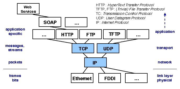
The protocols used on the Internet illustrate the above notions. The Internet is an interconnection of networks of various kinds and sizes, using a variety of physical communication links. At the upper end, applications are organized in levels, and protocols carrying out common functions are shared by several applications.
Chapters/XComm/Figs/internet.gif
Figure 4.3: The Internet protocol stack
The key of the success of the Internet is the organization shown on Figure 4.3: a single protocol, the Internet Protocol (IP) provides a common means for transferring packets (fixed size chunks of bits) from one node to another one, regardless of the underlying physical infrastructure and specific protocols. The level at which IP operates is called the network level. At this level, the machines (or hosts) connected to the various networks are designated by IP addresses, a naming scheme that uniquely identifies a (host, network) pair. The networks are interconnected by communication devices called routers, which implement the IP protocol by forwarding the packets to their destination. This forwarding function is based on routing tables, which are periodically updated to reflect the current traffic and link availability conditions.
At the next level up (the transport level), two protocols use IP to provide basic communication facilities to applications. UDP (User Datagram Protocol) is a connectionless protocol that allows single message exchange with no guarantees. TCP (Transmission Control Protocol) is a connection-oriented protocol that allows the bidirectional transfer of byte streams with order preservation, flow control, and fault tolerance capabilities.
TCP and UDP are called transport protocols. Contrary to IP, they are end to end protocols, i.e., the intermediate nodes used for communication between two hosts are not visible. End points for communication on each host are identified by port numbers; this allows a host to be engaged in several different exchanges. In addition, port numbers are used to identify a service on a server; fixed port numbers are allocated, by convention, to the most common services, such as mail, telnet, ftp, etc.
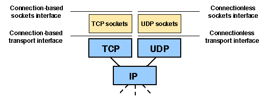
Most applications use TCP and UDP through sockets, a common interface provided by current operating systems (Figure 4.4).
Chapters/XComm/Figs/transport.gif
Figure 4.4: The transport interface
A socket is an end point of a two-way communication link set up between two processes, which may run on the same machine or on different machines. A socket is associated with a port number. There are two kinds of sockets: stream sockets (or TCP sockets), which allow connection-oriented communication with character streams using TCP, and datagram sockets (or UDP sockets), which allow connectionless communication with messages using UDP. Libraries and APIs for using sockets are available in common programming languages, including C and Java.
Details on socket programming may be found in [Stevens et al. 2004]. The architecture of the Internet is described in [Peterson and Davie 2003], [Kurose and Ross 2004].

4.4  Middleware and Application-level Protocols

Middleware, by its nature, consists of protocol stacks running at the application level. In most cases, the base level of middleware protocols is the transport level, and the protocols are implemented using the sockets interface. Examples of middleware protocols examined further in this book are RTP (see 4.6.3) and GIOP/IIOP (see 5.3.1 ).
One particular way of implementing a middleware layer is by defining a new network on top of an existing one, with additional properties. This is an instance of the virtualization approach described in 2.2.1 .
Such a virtual (or logical) network is called an overlay network. The term "overlay" refers to the fact that the functions of the new network are implemented in a set of nodes on the existing network, without interfering with the internal structure of that network. Note that this principle is used at several levels in the Internet itself: for example, the TCP transport layer is an overlay network built over the network (IP) layer, to provide additional properties such as connection-oriented communication and flow control.
In this section, we briefly discuss the main uses and properties of overlay networks. We then illustrate middleware or application-level protocols with the example of gossip protocols, a class of algorithms that finds a number of applications in large scale networks.

4.4.1  Overlay Networks

Overlay networks have been used to implement a variety of functions, some of which are listed below.
Most existing overlay networks either implement a transport layer (i.e., they are built on top of a network layer, usually IP), or an application-level layer (i.e., they are built on top of a transport layer).
The advantages and drawbacks of overlay networks may be appreciated by comparing two alternative ways of providing a given function to applications in a network: through programs running on the nodes of an overlay network or through code in the routers. This discussion is inspired from [Jannotti et al. 2000], to which we refer for further details.
An overlay network has the following benefits:
On the other hand, the designer of an overlay network is faced with the following problems.
It is difficult to draw a uniform conclusion, since the trade-off between benefits and defects must be appreciated for each single application. However, the ease of deployment and adaptability of overlay networks makes them a major asset for experiments. In many cases (e.g., if the size of the network is limited), the efficiency is acceptable, so that the overlay network may be used as a long standing solution as well.

4.4.2  Gossip Protocols

Gossip (also called epidemic) protocols are a class of application-level communication protocols based on probabilistic methods. Their main use is information dissemination in a large scale, dynamically changing network, which makes them well suited for peer to peer environments.
Gossip protocols are based on the paradigm of random propagation in a large population, examples of which are the epidemic spread of a contagious disease or the propagation of a rumor via gossip talk.
Consider the problem of multicasting a message to a given population of recipients (e.g., nodes on a network). A gossip protocol works as follows. When a member of the population receives the message, it forwards it to a randomly selected set of other members. The initial sender starts the process in the same way. The process of random selection is central in a gossip algorithm. In the standard version of the protocol, the subset of recipients at each stage has a fixed size, called the fanout (noted f), and the members of the subset are chosen with uniform probability among the whole population.
The above algorithm is a form of flooding, and a given member will likely receive the same message several times. Since resources are finite, some bounds need to be set. Therefore, additional parameters of the protocol are the buffer capacity (noted b) of a member (i.e., the maximum number of messages that it may hold), and the number of times (noted t) that a member propagates a given message (the cases t = 1 and t unbounded are known as "infect and die" and "infect forever", respectively, with the epidemic disease analogy).
A central question is the following: under which conditions will a gossip-based broadcast protocol approach the coverage of a deterministic one? Define an atomic broadcast as one that reaches every member of the population. Let n be the size of the population. Assuming that b, the buffer size, is unbounded, the proportion p of broadcasts that are atomic (or the probability of a given broadcast to be atomic), is determined by the value of t and f. It can be shown that, to maintain the value of p when n increases, either f or t must increase as a function of n. As an example, suppose t = 1. Then the algorithm exhibits a bimodal behavior when f varies for a fixed n: when f is less than log(n), the proportion of atomic broadcasts is close to 0; when f > log(n), the proportion increases with f, and reaches 1 for a high enough value of (typically 2 log(n)).
Thus, gossip-based broadcast appears to be a powerful tool, with the advantages of simplicity and independence on the topology of the network. The load for each participant is moderate. Because of their highly redundant nature, gossip protocols tolerate node failures. The random selection of receivers at each stage also makes them resistant to transient network failures.
The actual situation is more complex than the above simple model. In particular:
Various solutions exist to the random selection problem. Interestingly, many solutions rely on gossip itself, as each node may propagate lists of nodes that it knows. In many cases, the protocol relies on selection in a local cache, and it has been shown that this process is roughly equivalent to that of a global selection. The robustness of gossip protocols to failures and attacks, and ways to improve it, is surveyed in [Alvisi et al. 2007].
Applications of gossip protocols may be roughly divided in three classes [Birman 2007]:
Gossip protocols are the subject of active research. A collection of recent articles [Kermarrec and van Steen 2007a] gives a picture of some recent results and open questions. In particular, [Kermarrec and van Steen 2007b] propose a general framework to describe and classify gossip protocols and [Birman 2007] discusses the advantages, limitations, and promises of gossip protocols.

4.5  Building a Communication System

In this section, we examine some architectural aspects of the process of building a communication system. The approach that we describe is based on abstraction and modular composition. Making explicit the structure of the communication system as an assembly of parts has a number of advantages: conceptual elegance; flexibility, including dynamic adaptation to changing operating conditions; provision of a testbed for alternative designs. A potential drawback is the performance penalty imposed by crossing the boundaries between parts; however, optimization techniques allow this overhead to be reduced to an acceptable level in most cases. A more detailed discussion of system composition may be found in Chapter 7 .
In 4.5.1, we briefly present the x-kernel, a framework that pioneered the area of a modular approach to the construction of communication systems. In 4.5.2, we describe more recent work, which exploits further progress in component-based models and building tools.

4.5.1  The x-kernel, an Object-based Framework for Protocols

The x-kernel project [Hutchinson and Peterson 1991] has defined a systematic way of building a communication system, using a generic framework.
The framework is object-oriented, i.e., the abstractions that it supports are represented by objects (the notion of an object is defined in 2.2.2 ). The framework is based on three main notions: protocols, sessions, and messages. As explained in 4.3.1, a protocol defines an abstract channel through which messages may be sent. A session is a concrete representation of such a channel: it exports the API that allows a user of the protocol to send and receive messages. A given protocol may support a number of different sessions, corresponding to different groups of participants.
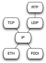
The general organization of the framework is as follows. A protocol graph is initially created, according to the specified protocol hierarchy; the arcs of the graph provide an explicit representation of the links between the protocols. Each protocol then acts as a session factory: it exports operations that allow sessions to be created and deleted according to the communication needs of the participants. An example of a protocol graph is shown on Figure 4.5
Chapters/XComm/Figs/protocol-graph.jpg
Figure 4.5: A protocol graph
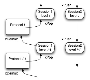
A session represents a communication channel operating under a certain protocol, and used by an application to exchange messages on a network. Like protocols, sessions are organized in levels, and a number of sessions may be simultaneously operating under a given protocol. At each level, a session provides an API through which messages may be sent or received. A message sent by an application using a session is propagated downwards in the protocol hierarchy, using an xPush operation at each session level. A message that arrives at the receiving end of a session on a site is propagated upwards in the protocol hierarchy, towards the application, using an xPop operation at each session level. The xPush and xPop operations actually implement the communication algorithms at each level of the protocol stack.
As explained in 4.3.1, send and receive are not symmetrical. A session is aware of the sessions below it (because session creation is a top-down process), but not of the sessions above it. Therefore a message propagating upwards needs to be demultiplexed, using the xDemux operation of the protocol at the next level up, to be propagated to the right session (or to the application, at the top level). This is done using a key present in the message. This process is summarized on Figure 4.6, which shows a message being received in Session 1 and a message being sent in Session 2.
Chapters/XComm/Figs/x-kernel.jpg
Figure 4.6: Message flow in the x-kernel
There are two approaches to organizing the processes in a communication system.
The organization of the x-kernel follows the latter model. This choice is motivated by efficiency reasons: in the process-per-protocol model, crossing a layer in the protocol hierarchy incurs the cost of a context switch, while in the process-per-message model the cost is that, much lower, of a procedure call. The cost of process (or thread) creation may be amortized by using pools.
A related approach is taken by the Scout system [Mosberger and Peterson 1996], in which execution is organized in "paths" (sequences of processing units, or stages, at the different protocol levels). Each path is run by a single thread.
The x-kernel has provided inspiration to a number of communication systems, among which Jonathan (described in more detail in 4.6), Appia [Miranda et al. 2001], Horus [van Renesse et al. 1996]. It is also the starting point of a more recent generation of frameworks, described in the next section.

4.5.2  Component-based Frameworks for Protocols

After the early contribution of the x-kernel and related systems, the evolution of the area of decomposition of network protocols has been influenced by two major trends:
We illustrate the component-based organization of communication protocols with three examples of experimental systems. These systems share the objectives of economy, flexibility, and explicit architectural representation, applied to various usage contexts.

The Click Modular Router

Click [Kohler et al. 2000] is a framework dedicated to the construction of configurable IP routers. The main function of a router is to implement the IP protocol by forwarding incoming packets to their appropriate next destination, which may be a host or another router. In addition, a router often performs other functions, such as packet tunneling and filtering, or implementing a firewall.
The objective of Click is to allow the program of a router to be easily configured and adapted. To that end, a router is built as an assembly of packet processing modules called elements. This assembly takes the form of a directed graph, whose edges represent the connections between the elements. This graph is an explicit representation of the architecture of the router.
Each element provides interface units called input and output ports, and a connection links an input port to an output port. Packets are sent on the connection, from the output port (source) to the input port (destination). There are two types of connections, "push" and "pull", according to whether the transfer of a packet is initiated by the source element or the destination element, respectively. Likewise, the type of a port may be defined (at router initialization time) as push, pull, or agnostic (i.e., neutral). An agnostic port behaves as push or pull if connected to a port of the push or pull type, respectively. The type of a connection is that of its ports. In addition to ports, an element may have a procedural interface accessible to other elements.
Validity rules define correct router configurations: a push output or a pull input port may not be the endpoint of more than one connection; a connection may not be set up between a push and a pull port; if an element acts as a filter between two agnostic ports, these ports must be used in the same way (push or pull). When the router is initialized, the connections are checked for validity, and the ports that were initially agnostic are set to the proper type according to the connections.
Contrary to the usual implementations of "ports", Click ports do not have built-in queues. A queue must be explicitly implemented as a Queue element, with a push input port and a pull output port.
A Click configuration is described by a simple declarative language, which allows elements and connections to be defined. Classes are defined for the usual elements, and compound classes may be defined by composing existing classes. A configuration description is used by the Click kernel to create and to initialize a configuration.
Chapters/XComm/Figs/click.jpg
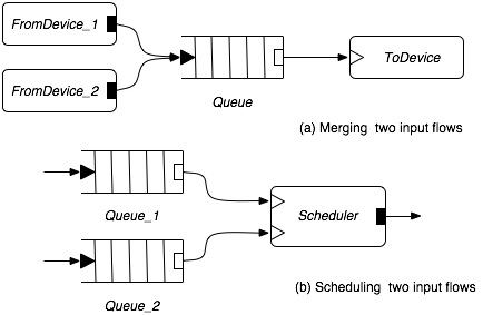
Figure 4.7: Elementary constructions in Click
Figure 4.7 illustrates two elementary configurations in Click. Output ports are represented by rectangles, input ports by triangles; push ports are black, pull ports are white. In configuration (a), packets coming from two devices are merged in a single flow, which is directed to an input device through a queue. In configuration (b), two input flows are input to a scheduler, which successively inputs packets from either flow according to its policy, and sends them on its output port. Note that in (a) the order of the packets entering the input device is determined by the order in which the packets are pushed into the queue, whereas in (b) the order of packets in the output flow is determined by the scheduler.
Elements are the units of CPU scheduling: an element that needs CPU time (e.g., because its push or pull methods are called) enters a task queue. A single thread is used to run this queue.
The Click framework has been used to construct actual IP routers. A typical router is made of a few tens of elements, and is highly configurable. Adding extensions and redefining scheduling and routing policies involve adding or reordering a few elements. Experience shows that the overhead due to the modular structure of the router is acceptable.

Dream: A Framework for Configurable Middleware

Dream [Leclercq et al. 2005] is a component-based framework dedicated to the construction of communication middleware. It provides a component library and a set of tools to build, configure and deploy middleware implementing various communication paradigms: group communication, message passing, event-reaction, publish-subscribe, etc. Dream builds upon the Fractal component framework (see 7.6 ).
Dream inherits the advantages of Fractal, among which hierarchical composition with component sharing, explicit definition of both provided and required interfaces, provision of an extensible management interface, which allows fine-grained control on binding and life-cycle at the component level.
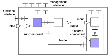
Figure 4.8 shows the architecture of a simple Dream system (which is also a component, by virtue of hierarchical composition).
Chapters/XComm/Figs/dream.jpg
Figure 4.8: System composition in Dream (from [Leclercq et al. 2005])
This figure illustrates the main aspects of composition in Dream: composite components (i.e., components containing other components), component sharing, connections (or bindings, in the Fractal terminology) between components. A binding may connect a required interface to a provided one (for synchronous method call), or an output port to an input port (for asynchronous message passing). Conformity rules (see 7.6 ) specify compatibility between the interfaces and therefore define legal bindings.
In addition, Dream provides features that facilitate the construction of communication systems:
While the overall composition structure of Dream is close to that of Click, there are a few important differences.
Dream has been used for full size experiments, among which a reimplementation of Joram (Java Open Reliable Asynchronous Messaging), a JMS compliant, industrial strength, open source middleware (6.7 ). This allows the Dream-based Joram to be easily reconfigured, possibly at run time. This benefit comes with a negligible penalty (about 2 percent in execution time and a fraction of a percent in memory footprint).

A Modular Network Layer for SensorNets

Wireless sensor networks, which are being developed for various applications, pose specific communication problems: achieving efficient and reliable communication with the constraint of scarce resources and noisy, time varying links. One proposal [Culler et al. 2005,Polastre et al. 2005] in response to these problems has been a unifying "narrow waist" architecture inspired by that of the Internet, with a single protocol, SP (Sensornet Protocol) providing an abstract layer for building higher level protocols while allowing multiple low-level protocols to coexist. SP differs from IP in two ways: it sits at an intermediate level between the link and network layers (i.e., it allows multiple network-level layers); and it does not impose a single format. Rather, it provides a set of services that abstract properties of the link layer (such as MAC format) and allow resource sharing between multiple link and network layer protocols operating simultaneously.
Building on SP, a modular network layer has been proposed [Ee et al. 2006], with the objective of minimizing redundancy by sharing fine-grain elements between protocols.
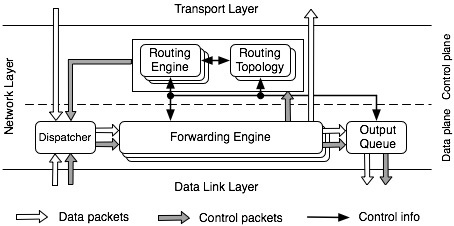
To that end, a decomposition of the network layer has been proposed, which identifies a "control plane" and a "data plane" (Figure 4.9). The data plane defines a data path between a dispatcher to an output queue through a forwarding engine. The control plane controls the forwarding engine and the output queue, through two modules: the routing engine and the routing topology. While the dispatcher and the output queue are unique, multiple instances of the other components may coexist.
Chapters/XComm/Figs/sensornet.jpg
Figure 4.9: Architecture of the Sensornet network layer (from [Ee et al. 2006])
The routing engine determines whether a packet should be forwarded, and, if that is the case, its next hop. The routing topology module exchanges information with its peers on other nodes to determine and to maintain the network topology. The forwarding engine queries the routing engine to obtain the next hop to which a packet must be sent.
In the experiments reported in [Ee et al. 2006], various existing protocols have been decomposed using specific instances of the basic elements described above. Experience shows that the objective of code reuse is actually achieved, with significant gains in memory occupation. As expected, there is a performance overhead with respect to a monolithic architecture. This penalty is considered acceptable in the context of sensor nets.

Conclusion on Component-based Communication Frameworks

The three case studies briefly discussed above illustrate a common trend in component-based communication systems, characterized by a search for common abstractions, an emphasis on architectural description with explicit structure and composition rules, and fine grain decomposition and sharing. The benefits are flexibility, adaptability, and economy (both conceptual and in terms of resources). There is a cost in terms of performance, which may be mitigated in most cases. A further step would be to derive the structure of the communication system from higher-level requirements. An example of research in this direction is described in [Loo et al. 2005]

4.6  Case Study: the Jonathan Communication Framework

Jonathan [Dumant et al. 1998] is a set of frameworks for building Object Request Brokers (ORBs). An overview of Jonathan, and a description of its binding framework, based on the export-bind pattern, is presented in . Here we describe the communication framework.

4.6.1  Principles of the Communication Framework

The Jonathan communication framework follows the general pattern introduced by the x-kernel and described in 4.5, i.e., a protocol graph whose base layer is at the transport level, used through Java sockets. We are not concerned about the lower levels.

Sessions

The main communication abstraction provided by Jonathan is a session (4.5), which represents a communication channel. A session supplies an interface for sending and receiving messages; actually two different interfaces ( Session_Low and Session_High) are respectively  provided for incoming and outgoing messages. In Jonathan, a protocol is essentially a session manager: it creates sessions, acts as a naming and binding context for these sessions, and provides them with communication resources. Like protocols, sessions are organized in a hierarchy. At the lowest level, a session relies on a basic communication mechanism called a connection, which provides an interface to send and to receive elementary messages (sequences of bytes). For instance, in the TCP-IP protocol suite, a connection provides the IpConnection interface and encapsulates a socket.
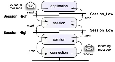
The main communication primitives are message send and receive. As explained in 4.3.1, they operate in different ways, due to the asynchronous nature of receiving. A read operation (implemented by a receive() method on a connection) blocks the executing thread until data is available on the input channel associated with the connection. When data becomes available (a message has arrived), the thread is unblocked, causing the message to be passed up the protocol stack by calling the "lower" interfaces of the sessions, in ascending order. On the other hand, an application process sends an outgoing message by calling the "higher" interface provided by a session. The message is then sent down the protocol stack by calling "higher" interfaces in descending order, down to the call of an emit method on the connection. Figure 4.10 gives an overview of this mechanism, which is described in further detail in Section .
Chapters/XComm/Figs/send-receive.jpg
Figure 4.10: Sending and receiving messages
Sessions are set up according to the Jonathan binding framework. On the server side, a protocol graph is first constructed by assembling elementary protocols. The protocol graph is a naming context, which provides the export method. The exported interface ( srv_itf) is the "lower" interface of a session (of type Session_Low), which provides the functionality of the server. The export method returns a session identifier (a name for the exported interface), which contains all the information needed to set up a communication with the server (e.g.,for TCP/IP, the IP address of the server and a port number). This information may be transmitted over the network and decoded by a client.
In order to be able to access the interface exported by a server, a client must call the bind method provided by a session identifier that designates the server, passing the client application's "lower" interface (clt_itf) as a parameter. The session identifier may be obtained from the network (e.g., through a name service), or it may be constructed locally using the server address and port number if these are known. The bind method returns an interface session of type Session_High, which may be used by the client to call the server. Messages from the server are directed to the client application, through the interface clt_itf provided as a parameter of the call to bind.
A general picture of the export-bind mechanism is outlined on Figure 4.11. Many details are omitted; these are provided in Section 4.6.2.
Chapters/XComm/Figs/export-bind.gif
Figure 4.11: The export-bind pattern for session setup
Actual communication relies on two services: chunks and (un)marshallers, that are provided, respectively, by the Jonathan resource library and the Jeremie presentation library. We describe these services briefly.
Typically, marshallers and unmarshallers are used as follows (this is a simplified example).
Sending a message composed of an integer i followed by a 8-byte string str followed by an object obj.


   Session_High session ...
   StdMarshallerFactory marshaller_factory ...
   ...
   Marshaller m = marshaller\_factory.newMarshaller();
   marshaller.writeInt(i);
   marshaller.writeString8(str);
   marshaller.writeValue(obj);
   session.send(marshaller);
   ...

Receiving the message sent by the above program sequence; the following sequence is supposed to be part of a method having Unmarshaller unmarshaller as a parameter.
   i=unmarshaller.readInt();}
   str=unmarshaller.writeString8();}
   obj=unmarshaller.readValue();}
   unmarshaller.close();}
   ...

   Marshallers and unmarshallers are created by marshaller factories. A marshaller factory is usually provided in the bootstrap configuration of Jonathan (see the configuration framework tutorial).

The Communication Infrastructure: Java Sockets

The first example (using Java sockets) does not involve Jonathan at all. It illustrates, at a fairly low level, the export-bind pattern of interaction that is further expanded in the following use cases. Consider a server that provides a service to a single client at a time (multiple clients are considered later on). The server selects a port (port 3456 in this example) and creates a server socket associated with that port. It then waits for client connections by calling accept() on the socket. When a client connects to port 3456 (this is done in the Socket constructor), accept() returns a new socket dedicated to exchanges with the client. The original socket remains available for new connections (if we do not create a new thread per client, only one client connection may be opened at a time).
Server

// create a new server socket associated with a specified port
   server_socket = new ServerSocket(3456);        
// wait for client connections:~a ``pseudo-export'' operation
   Socket socket = server_socket.accept();            
// socket is now available for communication with client                                                                         

Client

// connecting to server: a ``pseudo-bind'' operation
   Socket socket = new Socket(hostname, 3456);  
// socket is now available for communication with server

In effect, the accept() call in the server program is equivalent to our export primitive, while the connect() implicitly called in the Socket constructor in the client program is equivalent to our bind primitive.
Note that the binding process always relies on an information shared by the client and the server (here, the host name and the port number). In the present case, this shared information is hardwired in the code. More elaborate methods are introduced in further examples.
The complete code of an example using this pattern (a simple echo server) may be found in the Sun Java tutorial:
http://java.sun.com/docs/books/tutorial/networking/sockets/

4.6.2  The TCP-IP Protocol

In this section, we present the implementation of the TCP-IP communication protocol in Jonathan. This is a typical example of the way communication frameworks are defined and used in Jonathan.

Overview of the TCP-IP Framework

The libs.protocols.tcpip package implements the session level, together with the "chunk provider" which allows a session to get input data from a connection. The libs.resources.tcpip package implements the connection level. The session and connection levels are described in the following sections.

The Session Level

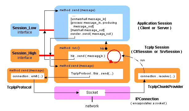
Since sessions play a central part in the communication framework, it is important to understand the interplay between sessions at different levels. We illustrate this by the example of TCP-IP (Figure 4.12). The general pattern outlined on this figure applies both on the client and on the server side. The main difference is that the server-side sessions are typically created by export, while the client-side sessions are created by bind.
Chapters/XComm/Figs/general-session.gif
Figure 4.12: Sessions in the TCP-IP Jonathan framework
At the lower level, we have a TcpIp session, which essentially encapsulates a connection to the network. It has two functions:
The TcpIp session has two slightly different forms ( TcpIpProtocol.CltSession and TcpIpProtocol.SrvSession) on the client and server side.
At the upper level, we have an application session, which provides the client or server functionality. The application session
It is important to emphasize the difference between the Session_High and Session_Low interfaces (especially since both interfaces include a method called send, which may seem confusing at first sight).
The classes ServerSession and ClientSession that implement the server and client application sessions of the Echo application have the following general outline.
class ServerSession implements Session_Low{
   ServerSession();
   static MarshallerFactory marshaller_factory;
   private int counter;             //internal state of session

   // the server method for accepting requests:
   //    - unmarshaller: the request message
   //    - sender: the local interface to the client

   public void send(UnMarshaller unmarshaller, Session_High sender){
      String theOutput = null;
      String theInput = unmarshaller.readString8();
      theOutput = counter + ":" + theInput;
      unmarshaller.close();
      Marshaller marshaller = marshaller_factory.newMarshaller();
      sender.prepare(marshaller);
      marshaller.writeString8(theOutput);
      sender.send(marshaller);
   }
}

class ClientSession implements Session_Low {
   static MarshallerFactory marshaller_factory;
   BufferedReader reader;           // for terminal input by client
   ClientSession(BufferedReader reader);
   this.reader = reader;}
   
   // the client method for accepting messages from server   
   //    - unmarshaller: the message   
   //    - session: the local interface to the server   

   public void send(UnMarshaller unmarshaller, Session_High session){
      String fromServer,input;
      System.out.print("Client: "); // prompting client   
      System.out.flush();   
      input = reader.readLine();   
      Marshaller marshaller = marshaller_factory.newMarshaller();   
      session.prepare(marshaller);   
      marshaller.writeString8(input);   
      session.send(marshaller);   
      fromServer = unmarshaller.readString8();   
      unmarshaller.close();
   }
}

The actual programs include, in addition, provision for exception handling and for nice termination of client sessions. They also contain provision for multiple clients, to be explained later on (cf. Section 4.6.2).

Setting up sessions

The mechanism for session setup uses the binding framework based on the export-bind pattern (3.3.2 ).
Both the server and the client start by an initial configuration phase and create an instance of TcpIpProtocol. Then each side instantiates a session as follows.
  • On the server side, an instance of ServerSession (the application session) is created. Then, a protocol graph is created with a single node (the instance of TcpIpProtocol). Finally, this graph exports the newly created application session: it creates an instance of SrvSession, with  the ServerSession instance as its higher level session, and  returns a session identifier that designates the exported session. Here is the code sequence that does this:
    Server:
    // configuring the system: creating factories
    // (described in the configuration tutorial)
    // creating a protocol instance (a naming context for sessions)
       TcpIpProtocol protocol = 
          new TcpIpProtocol(<parameters, to be described later>);
    
    // creating and exporting a new session
       SessionIdentifier session_id =
          protocol.newProtocolGraph(port).export (new ServerSession());   
    // if no port specified, selects an unused port


  • On the client side, a new session identifier (participant) is created to designate the remote server (In this version, we still assume that the name of the server host and the server port are known by the client). An instance of ClientSession (the application session) is created. Finally, the bind method is called on the participant identifier: it creates a new instance of CltSession, with the ClientSession instance as its higher level session, and returns a session identifier that designates the exported session. Here is the code sequence that does this:
    Client:
    // configuring the system: creating factories
    // (described in the configuration tutorial)
    // creating reader, getting server hostname and port
    
    // creating a protocol instance (a naming context for sessions)
       TcpIpProtocol protocol =
          new TcpIpProtocol(<parameters, to be described later>);
    
    // preparing for connection to server
       IpSessionIdentifier participant =
          protocol.newSessionIdentifier(hostname,port) ;
    
    // creating client-side session and connecting to server
       Session_High session = participant.bind (new ClientSession(reader)) ;
    // session is now available for communication with server}


From this point on, the core of the program runs in the application programs, i.e., the ClientSession and ServerSession classes, as described above.

The Connection Level

The interfaces provided by the session level abstract away (in the send methods) the low-level message transmission mechanism. This mechanism is defined at the connection level and (in the current implementation) relies on two classes: JConnectionMgr defines generic mechanisms for using socket-based connections, and IPv4ConnectionFactory provides a specific implementation of these mechanisms. The main abstraction at this level is the connection (instance of IpConnection), which encapsulates a socket.
For completeness, we now give a summary explanation of the mechanisms for message input. Recall that CltSession and SrvSession are the client and server incarnations, respectively, of the generic TcpIp session described above (in the code, both classes derive from a common abstract class, TcpIpProtocol.Session). This class extends Runnable, i.e., its instances are executed as independent threads activated by a run() method, which is called when a message is received. This is done through the TcpIpProtocol.TcpChunkProvider class, which encapsulates a socket input stream (through an IpConnection), and delivers messages as "chunks" (a Chunk is the abstraction provided by Jonathan to efficiently use data of variable length). This class has two main methods, prepare() and close(), which are respectively called as a prelude and postlude of all input operations performed through an Unmarshaller on the input stream. A TcpChunkProvider contains a data cache,which is used as follows.
  • prepare() delivers the contents of the cache (if not empty) and attempts to read further data into the cache from the underlying connection(the input stream);

  • close() is used to close the chunk provider if it is no longer used; if the cache is not empty, the session thread is reactivated, so the session may read the remaining data.

Thus the chunk provider effectively acts as a data pump that injects incoming messages into the TcpIp session, which in turn sends them to the upper level application session.

Putting it all together

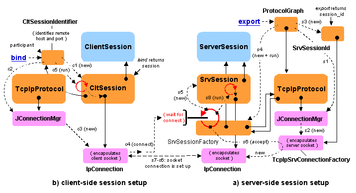
We now describe in detail the internal workings of the export-bind operations. An overview of these operations is given in Figure 4.13 which gives a more detailed picture of the process outlined on Figure 4.11.
Chapters/XComm/Figs/session-setup.gif
Figure 4.13: Creating client and server sessions
Calling the export method on ProtocolGraph has the following effect (s1, c1, etc. refer to the tags that designate the server and client operations on Figure 4.13).
  • The newSrvConnectionFactory(port) method is called on JConnectionMgr (s1). This creates a new instance of a TcpIpSrvConnectionFactory (s2), which encapsulates a server socket bound to the port provided as parameter (if 0, an available port is selected).

  • A new instance (session_id) of SrvSessionId is created (s3); it contains the host name of the server and the port number of the server socket.

  • A new instance of SrvSessionFactory is created (s4); it has references to session_id, to the exported ServerSession and to the TcpIpProtocol.

  • A new thread is started to execute the run() method of the SrvSessionFactory. The first action of this method is to create a new instance of SrvSession (s5).

  • The newConnection method is called on the TcpIpSrvConnectionFactory. This method actually calls an accept() on the underlying server socket (s6). This is a blocking call. The server now waits for a connect() operation from a client.

  • When connect() is called from a client (see client description below, step c4), a new socket is created and connected to the client socket (s7-c6).

  • A new thread is created to execute the run() method of SrvSession (s8). This in turns starts reading messages from the socket, as explained in the description of connections.

Calling the bind method on CltSessionIdentifier has the following effect.
  • A new instance of CltSession is created (c1).

  • The newCltConnection method is called on JConnectionMgr (c2). This creates a new socket (c3), encapsulated in a Connection, an implementation of the IpConnection interface.

  • The socket tries to connect() to the remote server, whose hostname and port number are included in the CltSessionIdentifier (c4).

  • Finally, a new thread is created to execute the run() method of CltSession (c5). This in turns starts reading messages from the socket, as explained in the description of connections.

Serving multiple clients

Two patterns may be used for serving multiple clients, according to whether the server maintains a common state shared by all clients or a distinct state for each client.
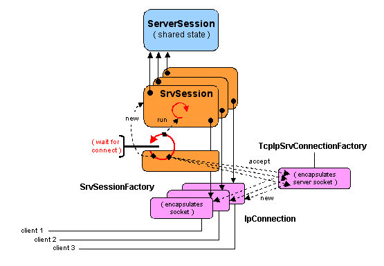
   Multiple connections with shared state. The mechanism described above allows several clients to connect to a single server, through the connection factory mechanism. If a new client binds to the server, a new connection is created (using the socket accept mechanism), as well as a new  SrvSession instance encapsulating this connection, together with a new thread. However, there is still a unique application session (ServerSession) , whose state is shared between all clients (Figure 4.14). This is illustrated in the example programs by adding state to the application session, in the form of an integer variable counter that is incremented after each client call. Multiple clients see a single instance on this variable.
Chapters/XComm/Figs/shared-state.gif
Figure 4.14: Multiple clients sharing a session state
If the application needs a per-client session state, then it is necessary to explicitly manage multiple sessions at the application level. This is done in the following example.
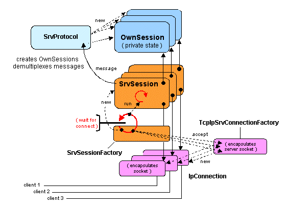
   Multiple connections with private state In this example, each client is associated with a distinct application-level session that maintains the client's own version of the state (in this case, the counter variable). This is achieved, on the server side by an instance of SrvProtocol, which has two functions: it acts as a factory that creates a new instance of the client session, OwnSession, when a new client connects; it acts as a demultiplexer that forwards the incoming messages to the appropriate OwnSession according to the identity of the sender. The factory is implemented as a hash table that contains an entry per session. The body of the application (in this case, the incrementation of the counter) is implemented by OwnSession.
Chapters/XComm/Figs/private-state.gif
Figure 4.15: Multiple clients, with a server session per client
The client side is identical to that of the previous application.

4.6.3  Other Communication Protocols

In this section, we examine the implementation in Jonathan of two other protocols: the IP Multicast Protocol and the Real Time Protocol (RTP). These implementations conform to the export-bind pattern as described in Section 4.6.1, with local variations. Then we present the Event Channel use case, which combines both protocols. A brief presentation of the GIOP protocol may be found in 5.5.1 .

The IP Multicast Protocol

As defined in IETF RFC 1112, "IP multicasting is the transmission of an IP datagram to a "host group", a set of zero or more hosts identified by a single IP destination address". IP addresses starting with 1110 (i.e., 224.0.0.1 to 239.255.255.255) are reserved for multicast. Groups are dynamic, i.e., a host may join or leave a group at any time; a host may be a member of several groups. A host need not be a member of a group to send a message to that group.
A particular class of Java sockets, java.net.MulticastSocket, is used in Jonathan as the base layer for implementing IP Multicast. A multicast socket s may subscribe to a host group g by executing s.joinGroup(g) and unsubscribe by executing s.leaveGroup(g). In order to send a message msg to a group g, a datagram must first be created by DatagramPacket d = new DatagramPacket(msg, msg.length, g, port), where port is the port to which socket s is bound. The datagram is then sent by executing s.send(d).
The Jonathan MulticastIpProtocol class manages MulticastIpSession sessions. Each session is dedicated to a ( IP Multicast address, port) network endpoint. A session may optionally be associated with an upper level session. In that case, it may send and receive messages, and a per session thread is used to wait for incoming messages. Otherwise, the session is only used to send messages.
In the IP Multicast protocol, there are no separate client and server roles; therefore there is no need to separate protocol graphs (which export servers) from session identifiers (which are used by clients to bind to servers). A single data structure, MulticastIpSessionIdentifier, is used for both functions (it implements SessionIdentifier and ProtocolGraph and thus provides both export and bind).
The sessions managed by this protocols are instances of class MulticastIpSession, which essentially provides two methods, send and run. In the current implementation, a single thread is created with each instance and waits on the multicast socket. The constructor is as follows:
  MulticastIpSession(MulticastIpSessionIdentifier sid, 
                Session_Low prev_protocol) throws IOException {
    socket=new MulticastSocket(sid.port());
    socket.joinGroup(sid.InetAddress());
    this.sid=sid;
    this.prev_protocol=prev_protocol;
    if(prev_protocol!=null) {
      reader =new Thread(this);
      cont = true;
      reader.start();
    }
  }

The reader threads executes the run() method which is a loop with the following overall structure (exceptions not shown):
  while (true) {
    socket.receive(packet); \\ a DatagramPacket
    extract message from packet
    send message to upper session, i.e., prev_protocol;
  }

The send(message) method does essentially this:
  encapsulate message into a DatagramPacket packet;
  socket.send(packet);

A MulticastIpSessionIdentifier contains three fields: address, port, and session. As explained above, the export and bind methods are very similar. Both create a new socket with an associated session. They only differ by the type of the returned value (an identifier for export, a session for bind); in addition, export needs to supply an upper level interface.
 118   public SessionIdentifier export(Session_Low hls) throws JonathanException {
 119      if (hls != null) {
 120        try {
 121               session = new MulticastIpSession(this,hls);
 122               return this;
 123        } catch (IOException e) {
 124               throw new ExportException(e);
 125        }
 126      } else {
 127        throw new ExportException("MulticastIpSessionIdentifier: no protocol low interface specified.");
 128      } 
 129   }  

 135   public Session_High bind(Session_Low hls)  throws JonathanException {
 136      try {
 137             return new MulticastIpSession(this,hls);
 138      } catch (IOException e) {
 139             throw new org.objectweb.jonathan.apis.binding.BindException(e);
 140      }
 141   }

As shown above, this creates a multicast socket using the port associated with the identifier, and spawns the reader thread if an upper (receiving) interface (hls) is provided (if not, the socket is only used for sending and does not need a waiting thread).

The RTP Protocol

RTP (Real-time Transport Protocol) is the Internet standard protocol for the transport of real-time data, including audio and video. RTP works on top of an existing transport protocol (usually UDP) and is designed to be independent of that protocol. RTP is composed of a real-time transport protocol (RTP proper), and of an RTP control protocol, RTCP, which monitors the quality of service.
Jonathan provides a partial implementation, RTPProtocol, of the RTP protocol (not including RTCP). RTP packets have a 12 byte header (defined by the RTPHeader class), which includes such information as sequence number and timestamp.
RTPProtocol provides the usual export and bind operations to its users:
  • export(Session_Low hls) is borne by a protocol graph built over the underlying protocol, and is called by a client providing hls interface for receiving messages. It returns a new RTPSessionIdentifier, which identifies an RTP session. It also creates a receiving front end for the hls interface, in the form of a decoder, an instance of the internal class RTPDecoder. The decoder extracts the header from an incoming message and forwards the message to the upper level interface (here hls).

  • bind(Session_Low client) is borne by an RTPSessionIdentifier. Its effect is to bind client to a new RTPDecoder (for receiving messages), and to return a coder implementing the Session_High interface for sending messages. This coder (an instance of the internal class RTPCoder) allows the client to prepare a header to be prepended to an outgoing message, incrementing the sequence number and timestamp as needed.

Use Case: Event Channel

Introduction  
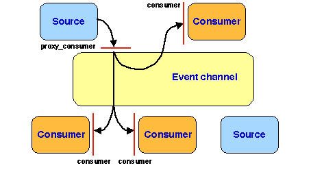
An event channel is a communication channel on which two types of entities may be connected: event sources and event consumers. When a source produces an event, in the form of a message, this message is delivered to all the consumers connected to the channel. The channel itself may be regarded as both an event source and consumer: it consumes events from the sources and delivers them to the consumers.
Two communication patterns may be used:
  • the "push" pattern, in which events are pushed by the sources into the channel, which in turn pushes them into the consumers;

  • the "pull" pattern, in which events are explicitly requested (pulled) by the consumers from the channel, which in turn tries to pull them from a source (this operation may block until events are produced).

In this example, we use the push pattern. The interface provided by the channel to event sources is that of a representative (a proxy) of the interface provided by the event consumers (Figure 4.16). Particular implementations of the event channel may provide specific guarantees for message delivery, in terms of reliability, ordering, or timeliness.
Chapters/XComm/Figs/event-channel.gif
Figure 4.16: An event channel based on the "push" pattern
Jonathan provides two implementations of a simple event channel, using a CORBA implementation (David, see 5.5 ) and a Java RMI implementation (Jeremie, see 5.4 ), respectively. Both rely on the same binder and event model; they essentially differ by the communication protocol. This presentation is based on the Jeremie version of the event channel.
The event channel provides the following interface, which defines the methods needed by event sources and consumers to connect to the channel using the "push" pattern:
public interface EventChannel extends java.rmi.Remote { // for use by RMI
  void addConsumer(Object consumer)
    throws JonathanException;  // adds a new consumer to the event channel
  void removeConsumer(Object consumer)
    throws JonathanException;  // removes a consumer (will no longer receive events)
  Object getConsumerProxy()
    throws JonathanException;  // returns a consumer proxy to be used by a source
}

Event channels are built by event channel factories. Class EventChannelFactory provides, among others, the following method:
  public EventChannel newEventChannel(String address, int port, String type) 
      throws JonathanException

which creates a new event channel built on the supplied host address and port. It also provides a class that implements the EventChannel interface defined above.
Using an Event Channel  
Like in the "Hello World" case described in the binding tutorial, a name server (in Jeremie, a registry) is used to register event channels. In this example, an event source creates the channel, registers it under a symbolic name of the form <// < registry host > < channel name > , and starts producing events. A prospective consumer retrieves a channel from the name server using its symbolic name, and subscribes to the channel; it then starts receiving messages transmitted on this channel.
The core of the main method of NewsSource, the program for event sources, is:
  EventChannel channel;
  EventChannelFactory channelFactory = 
     EventChannelFactoryFactory.newEventChannelFactory(NewsSource.class);
  channel=channelFactory.newEventChannel(address,port,"NewsChannel");
  Naming.rebind("//"+args[3]+"/"+args[2], channel); // //<registry host><channel name>
  System.out.println("Ready...");

  NewsTicker ticker=(NewsTicker)channel.getConsumerProxy(); 
  NewsSource producer=new NewsSource(ticker);
  producer.produce();// produce is the event generator method of NewSource class
                     // it includes a call to the NewsTicker method: ticker.latestNews

The core of the main method of NewsConsumer, the program for event consumers, is:
  System.setSecurityManager(new RMISecurityManager());                   
  channelName=args[0];
  EventChannel channel=
     (EventChannel) Naming.lookup("//" + args[1] + "/" + channelName);
  if(channel==null) {
     System.err.println("Channel "+ channelName + " not found");
     System.exit(1);
  }
  channel.addConsumer(new NewsConsumer());

The NewsTicker interface shared by source and consumer classes consists of the method latestNews(String msgs[]) activated when an event is produced. This method is implemented in the NewsConsumer class; it simply displays the incoming messages on the screen:
  public void latestNews(String msgs[]) {
     for(int i=0;i<msgs.length;i++)
      System.out.println(msgs[i]);
  }

Event Channel Implementation  
The implementation of the event channel relies on two components that closely interact: the event channel factory, EventChannelFactory, and the event binder, EBinder. The role of the factory is to deliver implementations of the EventChannel interface, both in the form of actual instances and in the form of stubs. The role of the binder is to provide an interface allowing both sources and consumers to connect to an event channel. The current implementation is hardwired to work with the RTP protocol on top of the IP Multicast protocol.
EBinder provides a specific class of identifiers, EIds. An EId designates an event channel built on a particular IP address and port number used by the underlying IP Multicast protocol. The two main methods are getProtocolGraph() and bind(), which are used as follows:
  • An event source that needs to connect to an event channel designated by EId channel_id executes channel_id.bind(), which returns a (Session_High) session on which the source will send events.

  • An event consumer that needs to connect to an event channel designated by EId channel_id executes EBinder.bindConsumer (consumer, channel_id), where consumer is the (Session_Low) interface provided by the consumer to receive events (note that this is a "push" interface, including a method send). bindConsumer is implemented as follows:
        ProtocolGraph protocol_graph = channel_id.getProtocolGraph();
        protocol_graph.export(consumer);


The usual export-bind pattern is again used here; getProtocolGraph() returns the protocol graph of the underlying RTP protocol, itself relying on IP Multicast; bind() returns a stub, created by a stub factory using the underlying RTP session.
An EventChannelFactory is created by an EventChannelFactoryFactory, which associates it with an EBinder. It implements special instances of stubs and skeletons targeted towards one-way invocation, and provides a specific implementation of EventChannel, that works as follows.
An instance of EventChannel is created by the constructor:
289  EventChannelImpl(String address, int port, String type, 
290        EventChannelFactory binder) throws JonathanException  {
291    id=(EBinder.EId)binder.getEBinder().newId(address,port,type);
292    SessionIdentifier ep=id.getSessionIdentifier();
293    Context hints = JContextFactory.instance.newContext();
294    hints.addElement("interface_type",String.class,type,(char) 0);
295    proxy=binder.newStub(ep,new Identifier[] {id}, hints);
296    hints.release();
297    this.binder=binder;
298  }

On line 291, a new EId is created by the EBinder, with the given address and port. On line 292, a new session is associated with this EId, using the underlying RTP and IP Multicast protocols. Finally, a proxy (stub) is created using this session. This proxy is ready to be delivered to any source willing to send events to the channel, through the following method:
328  public Object  getConsumerProxy() throws JonathanException {
329     return proxy;
330  }

A consumer connects to the event channel by calling the following method:
301    public void addConsumer(Object consumer) throws JonathanException {
302       a: if(binder==null) {
303          if (proxy instanceof StdStub) {
304             Identifier[] ids =
305                ((JRMIRef) ((StdStub) proxy).getRef()).getIdentifiers();
306             Object cid;
307             for (int i = 0; i < ids.length; i++) {
308                cid = ids[i];
309                while (cid instanceof Identifier) {
310                   if (cid instanceof EBinder.EId) {
311                      id = (EBinder.EId) cid;
312                      binder = (EventChannelFactory) id.getContext();
313                      break a;
314                   } else {
315                      cid = ((Identifier) cid).resolve();
316                   }     
317                }
318             }
319          }
320          throw new BindException("Unbound channel");
321       }
322       binder.getEBinder().bindConsumer(new OneWaySkeleton(consumer),id);
323    }

The key operation here is on line 322: the consumer builds a skeleton that will act as an event receiver interface for it, then binds that skeleton to the event channel using the bindConsumer method of the EBinder, as described above. Lines 302 to 321 illustrate another (classical) situation in the binding process: if the factory associated with the channel is not known (e.g., because the event channel reference has been sent over the network), the method tries to retrieve it using one of the identifiers associated with the stub, by iteratively resolving the identifier chain until the factory (binder) is found, or until the search fails.

4.6.4  Conclusion

Jonathan is based on the ideas introduced by the x-kernel, but improves on the following aspects:
  • It follows a systematic approach to naming and binding through the use of the export-bind pattern (3.3.3 )

  • It is based on an object-oriented language (Java); the objects defined in the framework are represented by Java objects.

The aspects related to deployment and configuration have not been described. Jonathan uses configuration files, which allow a configuration description to be separated from the code of the implementation.
Although Jonathan itself is no longer in use, its main design principles have been adopted by Carol [Carol 2005], an open source framework that provides a common base for building Remote Method Invocation (RMI) implementations (5.4 ).

4.7  Historical Note

Communication systems cover a wide area, and a discussion of their history is well outside the scope of this book. In accordance with our general approach, we restrict our interest to networking systems (the infrastructure upon which middleware is built), and we briefly examine their evolution from an architectural point of view.
Although dedicated networks existed before this period, interest in networking started in the mid 1960s (packet switching techniques were developed in the early 1960s and the first nodes of the ARPAnet were deployed in 1969). The notion of a protocol (then called a "message protocol") was already present at that time, as a systematic approach to the problem of interconnecting heterogeneous computers.
As the use of networks was developing, the need for standards for the interconnection of heterogeneous computers was recognized. In 1977, the International Standards Organization (ISO) started work that led to the proposal of the 7-layer OSI reference model [Zimmermann 1980]. By that time, however, the main protocols of the future global Internet (IP, TCP, and UDP) were already in wide use, and became the de facto standards, while the OSI model essentially remained a common conceptual framework.
The Internet underwent a major evolution in the mid-1980s, in response to the increase in the number of its nodes: the introduction of the Domain Name System (DNS), and the extension of TCP to achieve congestion control. A brief history of the Internet, written by its main actors, may be found in [Leiner et al. 2003].
The 1990s were marked by important changes. The advent of the World Wide Web opened the Internet to a wide audience and led the way to a variety of distributed applications. At about the same time, the first object-based middleware systems appeared, stressing the importance of application-level protocols. New applications imposed more stringent requirements on the communication protocols, both on the functional aspects (e.g., multicast, totally ordered broadcast) and on quality of service (performance, reliability, security).
In the 2000s, two main trends are visible: the development of new usages of the Internet, exemplified by overlay networks (e.g., [Andersen et al. 2001]) for various functions, from content distribution to peer to peer systems; and the rise of wireless communications [Stallings 2005], which generates new forms of access to the Internet, but also wholly new application areas such as sensor networks [Zhao and Guibas 2004] or spontaneous ad hoc networks. Both trends are leading to a reassessment of the basic services provided by the Internet (whose main transport protocols are still basically those developed in the 1980s) and to the search for new architectural patterns, of which the SensorNet research (4.5.2) is a typical example. Peer to peer and ad hoc networks call for new application-level protocols, such as gossip-based algorithms [Kermarrec and van Steen 2007a].
On the architecture front, the x-kernel [Hutchinson and Peterson 1991,Abbott and Peterson 1993] and related systems opened the way to a systematic approach to the modular design of communication protocols. Initially based on objects in the 1990s, this approach followed the transition from objects to components and is now applied to the new above-mentioned applications areas. The trend towards fine-grain protocol decomposition (as illustrated in 4.5.2) is imposed both by economy of resource usage and by the search for increased adaptability and customization. The strive for a balance between abstraction and efficiency, an everlasting concern, is still present under new forms.

References

[Abbott and Peterson 1993]
Abbott, M. B. and Peterson, L. L. (1993). A language-based approach to protocol implementation. IEEE ACM Transactions on Networking, 1(1):4-19.
[Aberer et al. 2005]
Aberer, K., Alima, L. O., Ghodsi, A., Girdzijauskas, S., Hauswirth, M., and Haridi, S. (2005). The essence of P2P: A reference architecture for overlay networks. In Proceedings of 5th IEEE International Conference on Peer-to-Peer Computing, pages 11-20, Konstanz, Germany.
[Alvisi et al. 2007]
Alvisi, L., Doumen, J., Guerraoui, R., Koldehofe, B., Li, H., van Renesse, R., and Tredan, G. (2007). How robust are gossip-based communication protocols? ACM SIGOPS Operating Systems Review, Special Issue on Gossip-Based Networking, pages 14-18.
[Andersen et al. 2001]
Andersen, D. G., Balakrishnan, H., Kaashoek, M. F., and Morris, R. (2001). Resilient Overlay Networks. In Proceedings of the Eighteenth ACM Symposium on Operating Systems Principles (SOSP'01), Banff, Canada.
[Babaoglu and Marzullo 1993]
Babaoglu, Ö. and Marzullo, K. (1993). Consistent Global States of Distributed Systems: Fundamental Concepts and Mechanisms. In Mullender, S., editor, Distributed Systems, pages 55-96. Addison-Wesley.
[Birman 2007]
Birman, K. (2007). How robust are gossip-based communication protocols? ACM SIGOPS Operating Systems Review, Special Issue on Gossip-Based Networking, pages 8-13.
[Carol 2005]
Carol (2005). Common Architecture for RMI ObjectWeb Layer. The ObjectWeb Consortium. http://carol.objectweb.org.
[Chockler et al. 2001]
Chockler, G. V., Keidar, I., and Vitenberg, R. (2001). Group Communication Specifications: a Comprehensive Study. ACM Computing Surveys, 33(4):427-469.
[Condie et al. 2005]
Condie, T., Hellerstein, J. M., Maniatis, P., Rhea, S., and Roscoe, T. (2005). Finally, a use for componentized transport protocols. In Proceedings of the Fourth Workshop on Hot Topics in Networks (HotNets IV), College Park, MD, USA.
[Coulouris et al. 2005]
Coulouris, G., Dollimore, J., and Kindberg, T. (2005). Distributed Systems - Concepts and Design. Addison-Wesley, 4th edition. 928 pp.
[Culler et al. 2005]
Culler, D., Dutta, P., Ee, C. T., Fonseca, R., Hui, J., Levis, P., Polastre, J., Shenker, S., Stoica, I., Tolle, G., and Zhao, J. (2005). Towards a Sensor Network Architecture: Lowering the Waistline. In Proceedings of the Tenth International Workshop on Hot Topics in Operating Systems (HotOS X), Santa Fe, NM, USA.
[Demers et al. 1987]
Demers, A., Greene, D., Hauser, C., Irish, W., Larson, J., Shenker, S., Sturgis, H., Swinehart, D., and Terry, D. (1987). Epidemic algorithms for replicated database maintenance. In Proceedings of the Sixth ACM Symposium on Principles of Distributed Computing (PODC '87), pages 1-12, New York, NY, USA. ACM.
[Dumant et al. 1998]
Dumant, B., Horn, F., Tran, F. D., and Stefani, J.-B. (1998). Jonathan: an Open Distributed Processing Environment in Java. In Davies, R., Raymond, K., and Seitz, J., editors, Proceedings of Middleware'98: IFIP International Conference on Distributed Systems Platforms and Open Distributed Processing, pages 175-190, The Lake District, UK. Springer.
[Ee et al. 2006]
Ee, C. T., Fonseca, R., Kim, S., Moon, D., Tavakoli, A., Culler, D., Shenker, S., and Stoica, I. (2006). A modular network layer for sensornets. In Proceedings of the Seventh Symposium on Operating Systems Design and Implementation (OSDI'06), pages 249-262, Seattle, WA, USA.
[Eugster et al. 2003]
Eugster, P.  Th., Felber, P., Guerraoui, R., and Kermarrec, A.-M. (2003). The Many Faces of Publish/Subscribe. ACM Computing Surveys, 35(2):114-131.
[Hadzilacos and Toueg 1993]
Hadzilacos, V. and Toueg, S. (1993). Fault-Tolerant Broadcasts and Related Problems. In Mullender, S., editor, Distributed Systems, pages 97-168. Addison-Wesley.
[Hutchinson and Peterson 1991]
Hutchinson, N. C. and Peterson, L. L. (1991). The x-Kernel: An architecture for implementing network protocols. IEEE Transactions on Software Engineering, 17(1):64-76.
[Jannotti et al. 2000]
Jannotti, J., Gifford, D. K., Johnson, K. L., Kaashoek, M. F., and O'Toole, Jr., J. W. (2000). Overcast: Reliable multicasting with an overlay network. In Proceedings of the Fourth Symposium on Operating Systems Design and Implementation (OSDI), pages 197-212, San Diego, CA, USA.
[Kermarrec and van Steen 2007a]
Kermarrec, A.-M. and van Steen, M., editors (2007a). Gossip-Based Computer Networking, volume 41(5), Special Topic of ACM Operating Systems Review.
[Kermarrec and van Steen 2007b]
Kermarrec, A.-M. and van Steen, M. (2007b). Gossiping in distributed systems. ACM SIGOPS Operating Systems Review, Special Issue on Gossip-Based Networking, pages 2-7.
[Kohler et al. 2000]
Kohler, E., Morris, R., Chen, B., Jannotti, J., and Kaashoek, M. F. (2000). The Click modular router. ACM Transactions on Computer Systems, 18(3):263-297.
[Kurose and Ross 2004]
Kurose, J. F. and Ross, K. W. (2004). Computer Networking: A Top-Down Approach Featuring the Internet, 2nd ed. Addison-Wesley.
[Lamport 1978]
Lamport, L. (1978). Time, Clocks, and the Ordering of Events in a Distributed System. Communications of the ACM, 21(7):558-56.
[Leclercq et al. 2005]
Leclercq, M., Quéma, V., and Stefani, J.-B. (2005). DREAM: a Component Framework for the Construction of Resource-Aware, Configurable MOMs. IEEE Distributed Systems Online, 6(9).
[Leiner et al. 2003]
Leiner, B. M., Cerf, V. G., Clark, D. D., Kahn, R. E., Kleinrock, L., Lynch, D. C., Postel, J., Roberts, L. G., and Wolff, S. (2003). A Brief History of the Internet. The Internet Society. http://www.isoc.org/internet/history/brief.shtml.
[Loo et al. 2005]
Loo, B., Condie, T., Hellerstein, J., Maniatis, P., Roscoe, T., and Stoica, I. (2005). Implementing declarative overlays. In Proceedings of the 20th ACM Symposium on Operating System Principles (SOSP'05), pages 75-90, Brighton, UK.
[Miranda et al. 2001]
Miranda, H., Pinto, A., and Rodrigues, L. (2001). Appia: A flexible protocol kernel supporting multiple coordinated channels. In Proc. 21st International conference on Distributed Computing Systems (ICDCS'01), pages 707-710, Phoenix, Arizona, USA. IEEE Computer Society.
[Mosberger and Peterson 1996]
Mosberger, D. and Peterson, L. L. (1996). Making paths explicit in the Scout operating system. In Operating Systems Design and Implementation (OSDI'96), pages 153-167.
[Peterson et al. 2004]
Peterson, L., Shenker, S., and Turner, J. (2004). Overcoming the Internet impasse through virtualization. In Third Workshop on Hot Topics in Networking (HotNets-III), San Diego, CA.
[Peterson and Davie 2003]
Peterson, L. L. and Davie, B. S. (2003). Computer Networks - a Systems Approach. Morgan Kaufmann, 3rd edition. 815 pp.
[Polastre et al. 2005]
Polastre, J., Hui, J., Levis, P., Zhao, J., Culler, D., Shenker, S., and Stoica, I. (2005). A unifying link abstraction for wireless sensor networks. In Proceedings of the Third ACM Conference on Embedded Networked Sensor Systems (SenSys).
[Ratnasamy et al. 2001]
Ratnasamy, S., Francis, P., Handley, M., Karp, R., and Shenker., S. (2001). A scalable content-addressable network. In Proceedings of the ACM SIGCOMM Symposium on Communication, Architecture, and Protocols, pages 161-172, San Diego, CA, USA.
[Rowstron and Druschel 2001]
Rowstron, A. and Druschel, P. (2001). Pastry: Scalable, decentralized object location and routing for large-scale peer-to-peer systems. In IFIP/ACM International Conference on Distributed Systems Platforms (Middleware), pages 329-350, Heidelberg, Germany.
[Saltzer et al. 1984]
Saltzer, J. H., Reed, D. P., and Clark, D. D. (1984). End-to-end arguments in system design. ACM Transactions on Computer Systems, 2(4):277-288.
[Stallings 2005]
Stallings, W. (2005). Wireless Communications & Networks. Prentice Hall, 2nd edition.
[Stevens et al. 2004]
Stevens, W. R., Fenner, B., and Rudoff, A. M. (2004). Unix Network Programming, vol. 1. Addison-Wesley.
[Stoica et al. 2003]
Stoica, I., Morris, R., Liben-Nowell, D., Karger, D. R., Kaashoek, M., Dabek, F., and Balakrishnan, H. (2003). Chord: a scalable peer-to-peer lookup protocol for Internet applications. IEEE/ACM Transactions on Networking, 11(1):17-32.
[Svetz et al. 1996]
Svetz, K., Randall, N., and Lepage, Y. (1996). MBone: Multicasting Tomorrows's Internet. IDG Books Worldwide. Online at http://www.savetz.com/mbone/.
[Tai and Rouvellou 2000]
Tai, S. and Rouvellou, I. (2000). Strategies for integrating messaging and distributed object transactions. In Sventek, J. and Coulson, G., editors, Middleware 2000, Proceedings IFIP/ACM International Conference on Distributed Systems Platforms, volume 1795 of Lecture Notes in Computer Science, pages 308-330. Springer-Verlag.
[Tanenbaum and van Steen 2006]
Tanenbaum, A. S. and van Steen, M. (2006). Distributed Systems: Principles and Paradigms. Prentice Hall, 2nd edition. 686 pp.
[van Renesse et al. 1996]
van Renesse, R., Birman, K. P., and Maffeis, S. (1996). Horus: a flexible group communication system. Communications of the ACM, 39(4):76-83.
[Wang 2001]
Wang, Z. (2001). Internet QoS. Morgan Kaufmann. 240 pp.
[Zhao and Guibas 2004]
Zhao, F. and Guibas, L. (2004). Wireless Sensor Networks: An Information Processing Approach. Morgan Kaufmann.
[Zimmermann 1980]
Zimmermann, H. (1980). OSI Reference Model-The ISO Model of Architecture for Open Systems Interconnection. IEEE Transactions on Communications, 28(4):425-432.

Footnotes:

1The terms synchronous (resp. asynchronous) are often used in place of blocking (resp. non-blocking). However, these terms have multiple meanings, and we use them in another context (4.1.2).
2When considering a distributed system (i.e., a set of processors connected by a communication system), synchrony also implies that there is a known bound on the relative speed ratio of any two processors.
3We only give an informal specification. An accurate and unambiguous specification of group communication properties is a delicate task, and is outside the scope of this discussion. See [Chockler et al. 2001].


File translated from TEX by TTH, version 3.40.
On 27 Feb 2009, 12:58.